
Installation Instructions

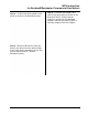
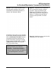
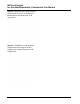
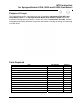
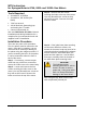
Table Of Contents
- Table of Contents
- 471-2000.pdf
- 471-2001.pdf
- 471-2002.pdf
- 471-2003.pdf
- 471-2004.pdf
- 471-2005.pdf
- 471-2006.pdf
- 471-2007.pdf
- 471-2008.pdf
- 471-2009.pdf
- 471-2010.pdf
- 471-2011.pdf
- 471-2012.pdf
- 471-2013.pdf
- 471-2014.pdf
- 471-2015.pdf
- 471-2016.pdf
- 471-2017.pdf
- 471-2018.pdf
- 471-2019.pdf
- 471-2020.pdf
- 471-2021.pdf
- 471-2022.pdf
- 471-2023.pdf
- 471-2026.pdf
- 471-2027.pdf
- 471-2028.pdf
- 471-2029.pdf
- 471-2030.pdf
- 471-2031.pdf
- 471-2032.pdf
- 471-2033.pdf
- 471-2034.pdf
- 471-2035.pdf
- 471-2036.pdf
- 471-2037.pdf
- 471-2038.pdf
- 471-2040.pdf
- 471-2041.pdf
- 471-2042.pdf
- 471-2043.pdf
- 471-2044.pdf
- 471-2045.pdf
- 471-2046.pdf
- 471-2047.pdf
- 471-2051.pdf
- 471-2052.pdf
- 471-2053.pdf
- 471-2054.pdf

MTU Instruction
for Rockwell/Equimeter Commercial Gas Meters
Step 4 – Position the lower gasket on the
meter as shown in the illustration below.
Step 5 – Break out the tab for either the
front or rear wire exit on the bottom edge
of the pulser body, depending on how you
plan to mount the MTU. (See the
illustration below.)
Step 6 – Assemble the couplers and
shaft to the pulser body as shown in the
illustration below. Ensure that the
magnet is mounted on the Standard
Coupler, and that the retaining shaft is
securely snapped into both couplers.
Page 115