
User's Manual
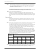
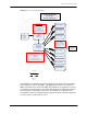
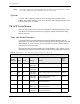
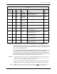
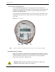
Table Of Contents
- Table of Contents
- Figures and Tables
- 1 - Introduction
- 2 - Functional Description
- 3 - Troubleshooting
- 4 - Specifications
- Acronyms
- Glossary
- Index

Universal Metering Transponder for kV2c™ Meter User Guide 29
Chapter 2 • Functional Description
Temperature Monitoring
As an additional safety feature, a solid state temperature sensor within the
UMT-C-KV module measures the internal temperature of the transponder PCB. If,
at any given time, the PCB temperature measured by the thermal sensor is greater
than the value stored in the “Temperature Threshold” register, the module will not
fire, even if the thermal limits controlled by the module firmware have not been
reached.
If any of the thermal limits are reached, (even if the measured temperature
indicates that the transponder's internal temperature is lower than the temperature
threshold) the transponder will not fire.
Two registers store transponder temperature data in degrees Celsius:
• Temperature Threshold register #736
• Internal Temperature register #735
The accuracy of the thermal sensor is within 6 °C in the range from - 40 °C to
+ 125 °C. The resolution of the “Internal Temperature” register is within 1 °C in
the range - 40 to + 125 °C. The Internal Temperature register is updated at
power-up and every 30 seconds thereafter.
When the thermal limit of the transponder is disabled through hardware, the
temperature sensing limits are bypassed and over-temperature safeguards will not
cause the transponder to cease Inbound transmissions.
Historical Data
All quantities captured by the meter data registers (at the time specified by the
Meter Data Daily Shift Time - Register #332) are stored for up to 7 days. Historical
Data also includes a copy of all the Meter Data Registers when the Billing Shift
occurs.
480 Volt Applications
As is widely recognized within the industry, whenever dealing with 480 volt
applications, there are some inherent challenges and risks associated with such
high voltages.
WARNING: The modes of failure in such applications may naturally be more
aggressive than in lower voltage applications. This is an issue with the
industry’s use of 480 volt applications and is by no means limited to GE meters.
Calibration Testing
All models support calibration testing of the integral watt-hour meter using
standard meter test equipment. When calibrating an kV2c meter, the optical port is
used to output pulses to the test equipment. The UMT-C-KV transponder uses a
serial link to the optical port for communication with the meter. The transponder
communication must be suspended during meter calibration. This can be done by
sending a time sync command containing a Date 0 Time 0x8700. This indicates an
invalid time and the transponder will not attempt to communicate.