
User's Manual
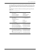
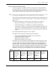
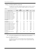
Table Of Contents
- Table of Contents
- Figures and Tables
- 1 - Introduction
- 2 - Functional Description
- 3 - Troubleshooting
- 4 - Specifications
- Acronyms
- Glossary
- Index

Universal Metering Transponder for kV2c™ Meter User Guide 19
Chapter 2 • Functional Description
Outage Duration Monitoring
For this user guide, an outage is defined as a loss of supply voltage sufficient to
cause the UMT-C-KV to power down. Outage duration is the interval between
power-down and power-up of the UMT-C-KV. The transponder maintains counts
of the number of outages in the Power Down Count register, ID 40.
N
OTE
Some features and capabilities of the transponder may not be supported, or may
be only partially supported by some versions of master station software.
There may be power interruptions too short for the UMT-C-KV transponder to see
it as an interruption. In this case the interruption is not considered an outage by the
UMT-C-KV.
The types of interruptions, per IEEE 1366, are divided into two categories:
• Momentary Interruptions - interruptions of less than five minutes.
• Sustained Interruptions - interruptions not classified as Momentary
Interruptions. (A utility can select any duration ranging from a minimum one
minute up to a maximum eight minutes in 2.5 second increments. However,
if modified, the interruption definition is no longer consistent with IEEE Std.
1366.)
The default Sustained Interruption value is 5 minutes.
The UMT-C-KV captures power interruption data as follows:
• Time stamp and duration of the 12 most recent interruptions.
• Sustained interruption duration data.
• Momentary interruption counter.
• Momentary interruption event counter.
The UMT-C-KV stores the daily interruption data for the last 35 days, but it will
not necessarily preserve the time stamp information for all the interruptions. An
example of the 35 Day Daily Interruption Summary Data (35D DISD) table is
shown in Table 2.5. The table represents the daily interruption summary data for
the last 35 days and has been designed to maintain the interruption data in a format
that supports the calculation of reliability indices such as those described in the
IEEE-Std. 1366. Refer to Power Reliability Indices for additional information.
Table 2.5
Example 35D DSID table
Date
Total
Sustained
Interruption
Duration for
the day
1
1. 20 Bits with 2.5 sec. resolution corresponds to 30.34 days (728 hours) duration.
Total
Sustained
Interruptions
during the
day
Total
Momentary
Interruptions
during the
day
Total
Momentary
Interruption
Events
during the
day
Data
Overflow
Alarms
16 Bits
20 Bits 5 Bits 7 Bits 6 Bits 2 Bits