UNIVERSAL METERING TRANSPONDER FOR kV2c METER USER GUIDE Y10577-TUM REV C
Proprietary Notice Information contained in this document is private to Distribution Control Systems, Inc., St. Louis, Missouri (DCSI). This information may not be published, reproduced, or otherwise disseminated without the express written authorization of DCSI. Any software or firmware described in this document is furnished under a license and may be used or copied only in accordance with the terms of such license.
Table of Contents Figures and Tables iii Chapter 1: Introduction 1 Safety Warnings and Symbols . Support . . . . . . . . . . . Product Returns . . . . . . . Related Documentation . . . . Let Us Know How We’re Doing . TWACS System Overview . . . . . . . . . . . . . . . . . . . . . . . . . . . . . . . . . . . . . . . . . . . . . . . . . . . . . . . . . . . . . . . . . . . . . . . . . . . . . . . . . . . . . . . . . . . . . . . . . . . . . . . . . . . . . . . . . . . . . . . . . . . .
Table of Contents Installation Procedure . . . . . Registers . . . . . . . . . . Thermal Limit . . . . . . . Changing the Sequence Delay . . . . . . . . . . . . . . . . . . . . . . . . . . . . . . . . . . . . . . . . . . . . . . . . . . . . . . . . . . . . . . . . . . . . . . . . . . . . . . . . Chapter 3: Troubleshooting 32 33 33 34 35 Performing Remote Analysis (TNS) . . . . Performing Remote Analysis (TWACS NG) . Field Troubleshooting. . . . . . . . . . Meter Shop Test System. .
Figures and Tables Figure 1.1 Figure 2.1 Figure 2.2 Figure 2.3 Table 2.1 Table 2.2 Table 2.3 Table 2.4 Table 2.5 Table 2.6 Table 2.7 Figure 2.4 Table 2.8 TWACS system . . . . . . . . . . . . . . . . . . . . . . . . . . . . . . . . . . . .7 UMT-C-KV module assembly. . . . . . . . . . . . . . . . . . . . . . . . . . . 10 View of UMT-C-KV module integrated within the kV2c meter . . . . . 11 Block diagram of the UMT-C-KV 2.0. . . . . . . . . . . . . . . . . . . . . .
Figures and Tables iv Universal Metering Transponder for kV2c™ Meter User Guide
CHAPTER 1 INTRODUCTION This chapter contains general information about this manual, important safety warnings to observe when using this product, contact information to receive support, and an overview of the TWACS system.
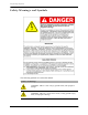
Safety Warnings and Symbols Safety Warnings and Symbols The following symbols are used in this manual. Symbols and Warnings WARNING: Indicate a risk of injury, possible death, and equipment damage. WARNING: Indicates a risk of electric shock, causing possible injury, death, and equipment damage.
Chapter 1 • Introduction Support The TWACS Portal (https://portal.twacs.com/) provides a wide range of information that can serve as a starting point when you have a question.
Related Documentation Related Documentation The following publications are referenced in this manual. The documents listed below plus the latest version of all other DCSI technical publications are available through the TWACS Portal (https://portal.twacs.com/). Meter Shop Test System Help Provides all the necessary details required for testing TWACS-enabled devices with the Meter Shop Test Tool software. Access the Help through the Meter Shop Test Tool software interface.
Chapter 1 • Introduction TWACS® NG System Help Built into the TWACS® NG interface, topic and index-searchable online system help is available. Access the Help through the software interface. The Help is not available through the TWACS Portal. TWACS® - ORION® for UMT Products User Guide (Y20100-TUM) Provides a brief overview of the TWACS-ORION system, explains how the TWACS-ORION system interfaces with the TWACS system, and describes the functions of the EMTR-3, HHTR-3, and ORION transmitter.
TWACS System Overview TWACS System Overview The TWACS system is a fixed network, utility communication system. Running at a centralized location, the TWACS operating software communicates with end points, such as meters, by way of existing power lines. The TWACS system allows full two-way access to and from the consumer’s meter, providing communication and control features for the Utility. The TWACS system consists of three levels of components (see Figure 1.
Chapter 1 • Introduction Figure 1.
TWACS System Overview 8 Universal Metering Transponder for kV2c™ Meter User Guide
CHAPTER 2 FUNCTIONAL DESCRIPTION This chapter provides an overview of the TWACS® system, explains how the Universal Metering Transponder for the GE kV2c meter (UMT-C-KV MP) interfaces with the TWACS system, and describes the functions of the transponder. This user guide provides feature and functionality information for Firmware version 2.00. Enhancements since version 1.
Daylight Saving Time The UMT-C-KV does not support the bi-annual Daylight Saving Time (DST) change as a scheduled routine. However, when the Master Station transmits a time sync command after the DST change has occurred, the RCE recognizes an offset exceeding the threshold limits (offset of one hour ± 15 seconds versus the 15 second threshold). The RCE master clock time is updated automatically.
Chapter 2 • Functional Description Figure 2.2 View of UMT-C-KV module integrated within the kV2c meter UMT-C-KV Module Functional Description of the UMT-C-KV The UMT-C-KV acts as an interface between the kV2c meter and TWACS powerline communication technology. It facilitates communication of kV2c meter quantities over the utility company distribution power lines. The diagram in Figure 2.3, “Block diagram of the UMT-C-KV 2.0”, illustrates the functionality of the UMT-C-KV. Table 2.
Functional Description of the UMT-C-KV Figure 2.3 Block diagram of the UMT-C-KV 2.0 GE k V 2 c /c + M e te r S E R IA L L IN K S E R IA L P O R T (T E S T ) POW ER LO SS D E T E C T IO N TW ACS U M T -C -K V M ic r o c o n tr o lle r TW ACS OUTBOUND D E T E C T IO N C IR C U IT R Y N O N V O L A T IL E MEMORY T W A C S IN B O U N D G E N E R A T IO N C IR C U IT R Y E M T R -3 -K V Table 2.
Chapter 2 • Functional Description Primary Functions The UMT-C-KV has two primary functions: • Communication - receive TWACS outbound commands and generate TWACS inbound responses. • Data retrieval - from customer-selected kV2c meter registers configured at meter/transponder integration. Each of these functions is described in the following sections and is graphically represented in Figure 2.3. Communication The UMT-C-KV communication process is described in the following sections.
Functional Description of the UMT-C-KV Two-way addresses are comprised of three fields: • Function - operational application, e.g. outage detection. Valid range 1-63. • Group - quantity of RCEs addressed by group. Valid range 1-262,143. • Unit - further subdivision of Group field and specific to channeling scheme. Valid range 1-255. Certain restrictions are placed on the assignment of multiple addresses.
Chapter 2 • Functional Description Two-way addresses are not associated with any particular function or port. The three addressing modes supported by the two-way address can be used to perform any function in the UMT-C-KV when the appropriate command parameters are used. The table below summarizes addresses and addressing modes supported by the UMT-C-KV. Table 2.
Functional Description of the UMT-C-KV The table below summarizes TWACS system communication features supported by the UMT-C-KV. Table 2.
Chapter 2 • Functional Description Meter Optical Port Support NOTE All serial port opcodes defined for the UMT-C-KV are accessible through the meter optical port. Communications between the meter optical port and the UMT-C-KV Test/Programming Serial Port begins with the transponder receiving a specified hexadecimal Identification Packet (IP) from the meter optical port - EE 80 20 00 00 01 20 20 75.
Functional Description of the UMT-C-KV Time-of-Use (TOU) The kV2c meter can perform time-of-use metering when required and programmed accordingly. The time-of-use schedule is loaded into the meter during meter/RCE integration. This schedule determines the times that the different TOU rates are in effect. The UMT-C-KV supports the kV2c meter TOU functionality. The UMT-C-KV transponder can be programmed to retrieve TOU data when its registers are appropriately mapped.
Chapter 2 • Functional Description Outage Duration Monitoring For this user guide, an outage is defined as a loss of supply voltage sufficient to cause the UMT-C-KV to power down. Outage duration is the interval between power-down and power-up of the UMT-C-KV. The transponder maintains counts of the number of outages in the Power Down Count register, ID 40.
Functional Description of the UMT-C-KV It is recommended that TWACS retrieves the daily interruption summary data at least every two weeks. The transponder will supply the following data as requested by the Master Station: • A power-down count in a cumulative format. • A summary of interruptions for the latest 12 time stamped interruptions. • The time stamped data for any given incident on any given day from the latest 12 time stamped interruption data. The data is read directly from the 35D DSID table.
Chapter 2 • Functional Description Power Reliability Indices The UMT-C-KV registers capture interruption data in the listed categories that can be used to calculate distribution reliability indices as specified in IEEE Std.1366, 2003 Edition, IEEE Guide for Electric Power Distribution Reliability Indices - a standard for power reliability within distribution systems, substations, circuits, and defined regions.
Functional Description of the UMT-C-KV Energy and Demand Measurement The UMT-C-KV can read the appropriate mapped registers of the kV2c meter on a scheduled basis and then store those readings in registers in its own memory. Table 2.
Chapter 2 • Functional Description Meter Constants The UMT-C-KV can store and communicate required meter values when those values are programmed in the meter and are mapped to a register in the UMT-C-KV. Values may include, but are not limited to: VT ratio, CT ratio, meter constant/Kh value, number of dials, meter type, etc. This allows the TWACS Master Station to automatically capture this information for billing without additional manual data entry.
Functional Description of the UMT-C-KV NOTE The Demand Reset and shift must occur simultaneously, and a Demand Reset can’t occur until 255 minutes after the Time/Date Stamp stored for the last Demand Reset. Therefore it is possible that a shift may be delayed by the 255-minute RCE Demand Lockout. Since the demand measurement may correspond to the utility’s billing system, the Demand Reset command ensures the integrity of the customer’s bill.
Chapter 2 • Functional Description Additional Features The following sections describe additional features of the UMT-C-KV transponder. Configuration Monitoring The UMT-C-KV monitors the Host Meter Configuration register in the kV2c meter. This register contains the programming information for the meter and is updated whenever the meter is reprogrammed. The UMT-C-KV reads and stores this configuration data in registers within its own memory.
Functional Description of the UMT-C-KV Voltage Agility The UMT-C-KV utilizes a range of voltages that enables the transponder to automatically use the voltage available to the commercial meter. The UMT-C-KV supports TWACS communication at any voltage (within the range of 120VAC-480VAC) that the meter form supports. Voltage Monitoring The UMT-C-KV obtains 3 phase voltage data every 5 minutes from the kV2c meter.
Chapter 2 • Functional Description Figure 2.4 RF operation block diagram RF Operation Block Diagram (TWACS-Orion Project) June 22, 2007 FCC ID: PN3Y72553-1 HHTR Data RF = PIC 18 LF242 902 -928 MHz UI = PIC 18 LF6720 8 MHz 7.2V NiMH 1600 mAH Regulated to 5V and 3.3V PC Data Transfer from /to HHTR RS-232 HHTR Handheld Transceiver 902-928 MHz kV2c™ with EMTR-3 KV RF Interface Orion Transmitter Orion Transmitter Orion Transmitter Orion Data 916 .
Functional Description of the UMT-C-KV The interface between the EMTR-3-KV and the UMT-C-KV is an Inter-Integrated Circuit (I2C) physical layer over which the Common Data Layer communications format operates. The UMT-C-KV performs the gateway function of connecting the EMTR-3-KV to the TWACS network. TWACS is able to read and write registers as well as execute Opcodes on the EMTR-3-KV using gateway functionality.
Chapter 2 • Functional Description Temperature Monitoring As an additional safety feature, a solid state temperature sensor within the UMT-C-KV module measures the internal temperature of the transponder PCB. If, at any given time, the PCB temperature measured by the thermal sensor is greater than the value stored in the “Temperature Threshold” register, the module will not fire, even if the thermal limits controlled by the module firmware have not been reached.
TWACS Installation NOTE If a power down occurs during calibration and the real-time clock has a valid time, the invalid time sync would need to be sent again. Options If a kV2c meter supports KYZ/Form A functionality, the operations of the UMT-C-KV module shall not, in any way, adversely affect the performance of the KYZ/Form A inputs or outputs.
Chapter 2 • Functional Description Type 101 Energy Per Count Model Number Class Form Voltage Service 8 20 8S/9S 120V-480V Autorange 4-Wire Polyphase Current Transformer Rated 0.00025 9 200 12S 120V-480V Autorange 3-Wire Polyphase Self-Contained 0.0025 10 320 12S 120V-480V Autorange 3-Wire Polyphase Self-Contained 0.00375 11 200 15S/16S 120V-480V Autorange 4-Wire Polyphase Self-Contained 0.0025 12 320 15S/16S 120V-480V Autorange 4-Wire Polyphase Self-Contained 0.
TWACS Installation Verification of Equipment Avoid damaging the equipment by verifying that the meter, defined by the nameplate, is compatible with the field socket wiring. Refer to the supported field installation wiring diagrams in the UMT-C-KV Field Installation Instructions located on the TWACS portal. Verify that the meter nameplate has the correct form number, class number, and voltage. Refer to Figure 2.5 for approximate location of this information on the meter label. Figure 2.
Chapter 2 • Functional Description To complete the installation process, the meter must be searched into the TWACS operating software. The following steps provide a general overview of this process. More detailed information is available in the TNS End User Guide and the TWACS Network Gateway Operational Process Guide. 1. Obtain, from the installer, the following information for the installed meter.
TWACS Installation Changing the Sequence Delay Normally it is not necessary to change the sequence delay. In the event that it is necessary to change the sequence delay for one or more rate classes (because of insufficient time between read commands to permit adequate transponder cooling), the Altimus Command Configuration window is used. Change the rate class sequence delay by following the instructions in the TNS System Administration chapter of the TNS End User Guide.
CHAPTER 3 TROUBLESHOOTING The purpose of this chapter is to provide DCSI customers with procedures that will assist in determining if a failed meter issue can be resolved in TNS or if a field visit is required. It is useful for installers and meter shop personnel. A failed meter or a meter with an invalid response can be the result of several factors including process, software, or hardware.
Performing Remote Analysis (TNS) 2. NOTE Determine if any error messages have occurred during AMR by checking the SCE Notification log for any associated hardware issues for the meters that are not communicating. The Notification log contains important information about the status of equipment and is automatically updated by TNS and the SCE.
Chapter 3 • Troubleshooting 7. Check for switching events which may have occurred in the system that possibly changed the communication path of the meter. (A communication path may have changed due to a physical move or a temporary switch to a different substation, phase, or other path component.) If the communication path has changed, you can use Pathmaps to update the TNS database.
Field Troubleshooting 6. NOTE If the previous steps determine that the meter has “Failed”, see on page 40 to return the meter. For additional information regarding remote troubleshooting, contact DCSI Customer Care (email care@twacs.com or call 1-800-892-9008) to speak with a Technical Support Engineer. Field Troubleshooting The most likely field troubleshooting scenario is a failure to display.
Chapter 3 • Troubleshooting NOTE IMPORTANT 5. Replace the meter and verify that the Communication icon (( )) appears on the meter display. This icon should display approximately 5-8 seconds after power up. The icon also displays briefly each minute thereafter, if a valid time sync has been received. 6. Use the Portable RCE Test Unit (PRTU) to confirm that the TWACS module is communicating. If a PRTU is not available, communication with the meter can be verified using TNS. 7.
Meter Shop Test System Figure 3.1 Optical port connection for kV2c meter NOTE To use the Meter Shop Test System serial communication option with a TWACS-enabled kV2c meter, you must have the correct SIA Cable Assembly (see Figure 3.2). Figure 3.
CHAPTER 4 SPECIFICATIONS This chapter contains electrical, environmental, and physical specifications for the UMT-C-KV transponder. Electrical Specifications Table 4.1 Electrical ratings Parameter Rating Line voltage Line frequency Quiescent power 120-480 VAC +/- 15% 60 Hz +/- 3.0 Hz 1.35 Watts not including TWACS or RF activity 25 amps RMS Yes on AC connection for TWACS None DC energy is provided by the kV2c Meter Electronics are not required to be electrically isolated from the power line.
Environmental Specifications Table 4.2 Compliance specifications Test Title Applicable Specification Surge withstand capability FT and OSC High voltage isolation on meter chassis ANSI/IEEE C.37.90.
Chapter 4 • Specifications Physical Specifications Table 4.4 Physical specifications Parameter Specification Size, weight, form factor Integrated dimensions Integrated weight Meter forms Installation instructions Meter socket 6.94 in. dia. x 8.2 in. lng. - Refer to General Electric specifications for kV2c meter kV2c meter w/ plastic cover 2 lbs. Integrated kV2c w/plastic cover 3.5 lbs. See Table 2.8, “Model number, class, meter form, voltage, service type, and energy”.
Additional Regulatory Data Table 4.4 Physical specifications Parameter Specification TWACS Serial Number Physical Tamper Protection Meter seal Supported Additional Regulatory Data The following is a tabulation of regulatory data found elsewhere in this manual and is required by the regulatory agencies of some countries.
Acronyms AC Alternating Current ADLC Asynchronous Data Link Communication AMR Automatic Meter Reading ANSI American National Standards Institution ASCII American National Standard Code for Information Exchange CIS Customer Information System DC Direct Current DCSI Distribution Control Systems, Inc.
Acronyms 46 Universal Metering Transponder for kV2c™ Meter User Guide
Glossary address An assigned unique, fixed number to a memory location in order to retrieve or store data. Automatic Meter Reading (AMR) Electronic accumulation and transport of meter data. The process of reading a meter from a remote location at scheduled times or on demand. bins A register to store the read data. bus An electrical common connection through which power is distributed. bus identification Identifies the substation bus to which DCSI equipment is connected.
Glossary Meter Shop Test Tool (MSTT) A software product developed by DCSI that performs troubleshooting and testing of meters. non-volatile data Data that is preserved even when the electrical power is off. phase The current supply conductors, other than the neutral conductor of a polyphase circuit, that usually carry the designation phase A, phase B, or phase C. Portable RCE Test Unit (PRTU) Portable unit for testing a TWACS-enabled device at a customer site.
Glossary Total Consumption (TC) The total electrical usage (in kWh) for the specified type of meter read. transponders Two-way field devices that can receive and send messages to and from the substation. TWACS Next Generation (TNG) or TWACS Net Server (TNS) Chief component of the entire Two-Way Automatic Communication System. Manages all collected metering and interval data as well as the connection between the utility and the consumer’s premises.
Glossary 50 Universal Metering Transponder for kV2c™ Meter User Guide
Index Numerics M 480 volt applications 29 maintenance 40 Master Station 6 Meter 39 meter data registers 26 meter map registers 26 meter shop testing 39 meter socket 12 microprocessor 12 A AC input voltage 25 addressing modes 15 TWACS-10 TWACS-20 15 15 Altimus Command Configuration 33 AMR 33 ANSI 12 N B nonvolatile memory 12 bus identification 33 O C On Request Read 33 outage duration 19 outage monitoring 28 outbound detection circuitry 12 calibration testing 29 care@twacs.
Index See Serial Time Unit 9 substation 33 Substation Communications Equipment 6 support 3 T Technical Support 3 temperature monitoring 29 theory of operation 9, 10 time synchronization 17, 25 time-of-use 18 TNS 6, 33 primary functions 6 TNS Operational Process Guide 4 transformer 25 troubleshooting field TWACS 38 three levels of components 6 TWACS-10 Communication Protocol 14 TWACS-20 Communication Protocol 14 two-way address 13 Two-Way Automatic Communication System inbound generation circuitry