Proprietary Notice Information contained in this document is private to Aclara Power-Line Systems Inc., St. Louis, Missouri. This information may not be published, reproduced, or otherwise disseminated without the express written authorization of Aclara. Any software or firmware described in this document is furnished under a license and may be used or copied only in accordance with the terms of such license.
Table of Contents Chapter 1: Introduction 1 Support . . . . . . . . . . . Product Returns . . . . . . . Related Documentation . . . . Let Us Know How We’re Doing . . . . . . . . . . . . . . . . . . . . . . . . . . . . . . . . . . . . . . . . . . . . . . . . . . . . . . . . . . . . . . . . . . . . . . . . . . . . . . . . . . . . . Chapter 2: Home Area Network Overview Components . . . . . . . . Aclara Integrated Meter . . In Home Display. . . . . . Programmable Thermostat .
Table of Contents ii Home Area Network Guide
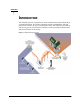
CHAPTER 1 INTRODUCTION The TWACS system is a fixed network, utility communication system. Running at a centralized location, the TWACS operating software communicates with end points, such as meters, by way of existing power lines. The TWACS system allows full two-way access to and from the consumer’s meter, providing communication and control features for the Utility. Figure 1.
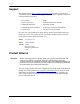
Support Support The TWACS Portal (http://customer.aclaratech.com) provides a wide range of information that can serve as a starting point when you have a question.
Chapter 1 • Introduction Related Documentation The following publications are referenced in this manual. The documents listed below plus the latest version of all other Aclara technical publications are available through the TWACS Portal (http://customer.aclaratech.com). Manual Title (Yxxxxx-TUM) Copy description from Related Documentation file in Tech Writing Reference Material > Standard Material > Related Documentation.fm.
Let Us Know How We’re Doing 4 Home Area Nework Guide
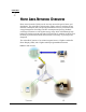
CHAPTER 2 HOME AREA NETWORK OVERVIEW Home Area Networks (HANs) are the next step toward the goal of smart grid distribution. The Aclara HAN is designed to supply end-users with the current demand, consumption data, and pricing information necessary for demand side energy management. Providing real time consumption and pricing feedback encourages consumers to self-regulate energy usage which will ultimately help balance the load across both peak and off-peak periods.
Each of these demonstration units (IHD, programmable thermostat, and RCE) are delivered in matched sets to facilitate installation and intercommunication. Each matched set is coded with a particular set number (see for set number identification), and components from sets are not interchangeable. (e.g. An IHD from set #2 may not be used with the programmable thermostat from set #1.) NOTE 6 The matched sets are for demonstration only. All production units will be interchangable.
Chapter 2 • Home Area Network Overview Components Aclara Integrated Meter The Aclara integrated meter functions as the hub of the HAN. It receives TWACS communication from the Master Station and relays this to the IHD and programmable thermostat. Similarly, it receives communication from the IHD and the programmable thermostat, and transfers this information back to the Master Station. The Aclara integrated meter consists of a UMT-R-FX transponder and a ZigBee module integrated with an L+G FOCUS meter.
Components In Home Display The Aclara IHD is a plug-in demand response component that receives messages, alerts, billing, and account status information from the utility via the RCE. The IHD displays this information for the end user, so that he or she may plan and adjust energy consumption accordingly. The IHD plugs into a standard 120 VAC outlet. Figure 2.3 Installed IHD NOTE: 8 Appearance of actual IHD may vary from image.
Chapter 2 • Home Area Network Overview Programmable Thermostat The programmable thermostat allows the utility to make adjustments based on pricing or current demand. Future versions will allow end users to temporarily opt out of the program, however the present version does not allow the consumer to override the utility settings. Figure 2.4 Installed programmable thermostat NOTE: Appearance of actual programmable thermostat may vary from image.
Functional Description Functional Description The HAN module receives power from the host device and has its own microcontroller, RF circuitry, and permanently attached antenna. The HAN module transmits and receives RF transmissions from an IHD and a programmable thermostat. The HAN module transmits and receives data using 16 channels spaced at 5 MHz intervals across the 2.4 GHz ISM band. The first channel used is at 2405 MHz, and the 16th channel is at 2480 MHz.
Chapter 2 • Home Area Network Overview Figure 2.
Functional Description Messaging The TNS HAN software is capable of sending 59 bytes of text to either the IHD or the thermostat. The number of bytes a HAN device will receive, however, may vary. The TNS operator has the option of specifying a display time duration, message importance, and/or requesting confirmation for each message. The message will appear in the HAN device display until the display time elapses, the message is cancelled, or a new message is sent. Figure 2.
Chapter 2 • Home Area Network Overview Pricing This option allows the TNS operator to send a pricing message consisting of a price value and a start time to the HAN device. A pricing message sent to the HAN device will remain active until a new pricing message is received. The HAN module will store up to 5 pricing messages. Figure 2.7 Price Message tab NOTE A pricing message cannot be cancelled, but it can be replaced with a new pricing message.
Functional Description Temperature Setback Selecting this tab allows the operator to send a Smart Energy Profile (SEP) load control command to the thermostat. These commands include the offset value, the start time and date, and command duration. Once a temperature setback command begins, it will remain active until the command duration expires or the start time of a new command is reached.
CHAPTER 3 INSTALLATION This chapter provides details about setting up the Aclara HAN. Follow the procedure in the order listed to ensure every the installation step is completed. Prerequisites Aclara personnel will help search the RCE into TNS, however there are steps that must be performed prior to Aclara’s arrival. If, at any time, you would like to speak with an Aclara representative about these instructions, please contact Aclara Customer Care at (800) 892-9008 or care@aclara.com. 1.
Prerequisites Residence Access Please ensure that the installation locations allow access to the interior of the residence during the time of installation. This is necessary to ensure the programmable thermostat and IHD are installed and operating correctly.
Chapter 3 • Installation Installation IHD Installation The IHD must be installed in the residence prior to the programmable thermostat. Programmable Thermostat Installation The programmable thermostats must be installed prior to Aclara’s arrival. Please refer to the operating and installation manual included with the programmable thermostat.
Installation 18 Home Area Network Guide
CHAPTER 4 METER SHOP TEST TOOL Setup 1. Insert the integrated meter into an appropriate meter socket. 2. Plug the IHD into a standard 120 VAC outlet. 3. Connect the Meter Shop Test Tool to the integrated meter. Once connected and powered up, proceed through the following functions of the HAN.
Interval Data 20 Home Area Nework Guide
SPECIFICATIONS The HAN module was designed in accordance with the IEEE 802.15.4 protocol. This section contains general, electrical, environmental, and physical specifications for the HAN module. Electrical Specifications Table 5.1 HAN module electrical ratings Parameter Rating Input Voltage Quiescent Current Current while transmitting RF Power Supply 11 to 17 VDC <15 mA @ 13 VDC <30 mA @ 13 VDC DC energy is provided by the host. Compliance Specifications NOTE Unless otherwise indicated, ANSI C12.
Environmental Specifications Environmental Specifications Table 5.3 HAN module environmental specifications Thermal Effect of Operating Temperature Aclara Specific Test -40°C to 70°C with and without solar load Humidity Effect of Relative Humidity 22 Aclara Specific Test 60°C for three 24 hour cycles or 85°C for one 24 hour cycle at 95 ±4 % relative humidity, non-condensing.
Chapter 5 • Specifications Physical Specifications Table 5.4 HAN module physical specifications Parameter Specification Approximate Weight < 1.0 oz. (28.4 g.) Dimensions 5.3" x 2.9" x .6" Additional Regulatory Data Table 5.5 HAN module labeling requirements Labeling Requirements The FCC ID and IC ID numbers are located on the module label as shown in Figure 5.1. The Aclara serial number, which is also the MAC address, is also displayed on this label. Figure 5.
Additional Regulatory Data The following is a tabulation of regulatory data found elsewhere in this manual and is required by the regulatory agencies of some countries. Table 5.6 HAN module regulatory data Parameter Specification Disclaimer noting that operation of the device is subject to conditions and that the device may not cause harmful interference and device must accept any interference received. Principles of device operation Regulatory Data note on page 10.
Index C care@aclara.
Index 26 Home Area Network Guide