
Instruction Manual


Automation Components, Inc.
2305 Pleasant View Road | Middleton, WI 53562
Phone: 1-888-967-5224 | Website: workaci.com
Page 4
Version: 6.0
I0000822
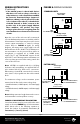
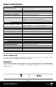
FIGURE 9: MULTIPLE TRANSMITTER CONNECTIONS
P
ower Supply
+ -
+ -
+ -
Temp.Transmitter #1
Temp.Transmitter #N
Temp.Transmitter #2
-VDC+
Controller
Gnd AI1 AI2 AI3
= Connections
AI
1 = Controller Input #1
AI
2 = Controller Input #2
AI
3 = Controller Input #3
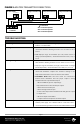
SOLUTION(S)
• No power to board - check voltage at power terminal - should be
between +8.5 and 32 VDC.
• RTD wires shorted. Disconnect sensor wires from terminal block and
check with ohmmeter. Reading should be close to either 100 or
1000 .
• RTD Improper range of transmitter (too low). Check current or
voltage (model dependent) - should be between 4-20 mA, 1-5 V, or
2-10 V.
• RTD opened. Disconnect sensor wires from terminal block and check
with ohmmeter. Reading should be close to either 100 or 1000 .
• Improper range of transmitter (too high). Check current or voltage
(model dependent) - should be between 4-20 mA, 1-5 V, or 2-10 V.
• Sensor check: Disconnect sensor wires from terminal block and
check with ohmmeter. Compare the resistance reading to the
Temperature vs Resistance curves located on ACI’s website.
• Transmitter check: Make sure sensor wires are connected to
terminal block. Determine that the proper output is being
transmitted based on predetermined span:
1. Go to ACI Website, Span to Output Page:
http://www.workaci.com/content/span-output
2. Enter the low end of the span
3. Enter the high end of the span
4. Click on the output of the transmitter. This will generate a span
to output chart.
5. Measure output of transmitter.
6. Compare measured output to calculated output
• Input power must be clean. Use twisted wires or shielded cable. RF
resistant power supply. Use a shielded cable to connect the sensor -
connect the shield to ground. Encase the board in a RF shielded enclosure.
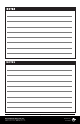
TROUBLESHOOTING
PROBLEM
No Reading
Reading too Low
Reading too High
Reading is Inaccurate
RF Interference