
Instruction Manual


Automation Components, Inc.
2305 Pleasant View Road | Middleton, WI 53562
Phone: 1-888-967-5224 | Website: workaci.com
Page 3
Version: 6.0
I0000822
WIRING INSTRUCTIONS
(Continued)
• If the 24 VDC power is shared with devices
that have coils such as relays, solenoids, or
other inductors, each coil must have an MOV,
DC Transorb, Transient Voltage Suppressor
(ACI Part: 142583), or diode placed across the
coil or inductor. The cathode, or banded side
of the DC Transorb or diode, connects to the
positive side of the power supply. Without
these snubbers, coils produce very large
voltage spikes when de-energizing that can
cause malfunction or destruc tion of electronic
circuits.
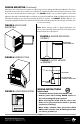
Open the cover of the enclosure. ACI recommends
16 to 26 AWG twisted pair wires or shielded cable for
all transmitters. Twisted pair may be used for 2-wire
current output transmitters or 3-wire for voltage
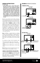
output. Refer to FIGURE 8 (right) for wiring
diagrams. All wiring must comply with local and
National Electric Codes. All ACI TT and TTM tempera-
ture transmitters can be powered from either an
unregulated or regulated 8.5 to 32VDC power
supply. The TT and TTM DO NOT support an AC
input. All TT and TTM temperature transmitters are
reverse polarity protected. After wiring, attach the
cover to the enclosure.
Note: All RTD’s are supplied with (2) or (3) ying
lead wires. ACI’s transmitters are supplied with a 2
pole terminal block for RTD sensor connections.
When wiring a 3 wire RTD, connect the (2) common
wires (same color) together into the same terminal
block.
The minimum voltage at the transmitter power
terminal is 8.5V after load resistor voltage drop.
• 249 load resistor (1-5 VDC output) = 13.5 V min supply
voltage
• 499 load resistor (2-10 VDC output) = 18.5 V min supply
voltage
Note: Adding extra wire length between the sensor
and transmitter board may aect accuracy.
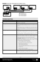
FORMULA FOR NUMBER OF TRANSMITTERS
Several transmitters may be powered from the same
supply as shown in FIGURE 9 (p. 4). Each transmitter
draws 25mA; refer to the following equation to
obtain the number of permissible transmitters: [#
Transmitters] = [Current] / (25 mA).
+VDC (Red Wire)
4 to 20mA Output
(White Wire)
RTD Wires
(100 Ohm RTD Brown Wires)
(1K Ohm RTD Black Wires)
+VDC (Red Wire)
GND (White Wire)
Voltage Output
(Yellow Wire)
(1 to 5, 2 to 10VDC)
RTD Wires
(100 Ohm RTD Brown Wires)
(1K Ohm RTD Black Wires)
Current Output
(4 to 20 mA)
Current Output
(4 to 20 mA)
+VDC
4 to 20mA Output
Voltage Output
(1 to 5, 2 to 10VDC)
Voltage Output
(1 to 5, 2 to 10VDC)
+VDC
GND
Voltage Output
(1 to 5, 2 to 10VDC)
+
-
GND
VOUT
RTD
+
-
RTD
SPAN
ZERO
SPANZERO
SPAN
ZERO
SPANZERO
POTTED UNITS
STANDARD UNITS
FIGURE 8: WIRING DIAGRAMS