
Instruction Manual


Automation Components, Inc.
2305 Pleasant View Road | Middleton, WI 53562
Phone: 1-888-967-5224 | Website: workaci.com
Page 2
Version: 6.0
I0000822
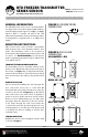
FIGURE 3: ENCLOSURE
MOUNTING
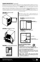
FIGURE 6: SENSOR MOUNTING
ON WALL
VAC
SENSOR MOUNTING (Continued)
Alternative, the senor may be mounted on walls using a 1/4” mounting clip (ACI Item #108169). The sensor
should be mounted in an area where air circulation is well-mixed and not blocked by obstructions. Slide
the sensor probe through the mounting clip - see FIGURE 6. Drill a 1/4” screw through the socket and
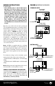
tighten to the wall. If a thermal buer is required, use a glycol kit (ACI Item #130127). Drill pilot holes for the
provided mounting screws. Use the mounting clip holes as a guide - see FIGURE 7. Drill the #10-16 x 1/2“
screws through the bracket holes and fasten it to the wall. Insert the bottle into the bracket, and make sure
it is seated securely.
Note: When using in tank or glycol application, the
sensor cannot be fully submerged. The end of the probe
must be kept above the liquid.
BULLET PROBE
1/4” MOUNTING CLIP
FIGURE 7: GLYCOL SENSOR
w/ BRACKET
SENSOR WIRES
GLYCOL BOTTLE AND
STANDARD 4” SENSOR PROBE
STEEL MOUNTING
BRACKET
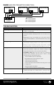
FIGURE 4: WIRE ROUTING
FIGURE 5: SENSOR MOUNTING
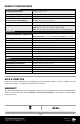
WIRING INSTRUCTIONS
PRECAUTIONS
• Transmitter must be powered by 24 VDC only.
• Remove power before wiring. NEVER connect or
disconnect wiring with power applied.
• When removing the shield from the sensor end,
make sure to properly trim the shield to prevent
any chance of shorting.
• When using a shielded cable, ground the shield
ONLY at the controller end. Grounding both ends
can cause a ground loop.