
PCI to Ultra SCSI RAID Controllers Installation Guide
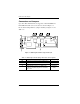
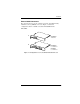

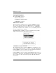
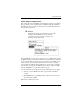
Table Of Contents
- Outside Front Cover
- Inside Front Cover
- Greetings/Please Notice/Our Policy
- About This Manual
- TABLE OF CONTENTS
- Chapter 1: Introduction
- Chapter 2: Preinstallation Planning
- Chapter 3: Installation
- Chapter 4: Controller Start-up
- Appendix A: Battery Backup Unit Option
- Appendix B: DAC960PG and DAC960PJ Specifications
- Appendix C: Error Messages
- Appendix D: Enclosure Management
- Appendix E: Regulatory Information
- Glossary
Connectors and Jumpers
3-2 DAC960PG and DAC960PJ Installation
Connectors and Jumpers
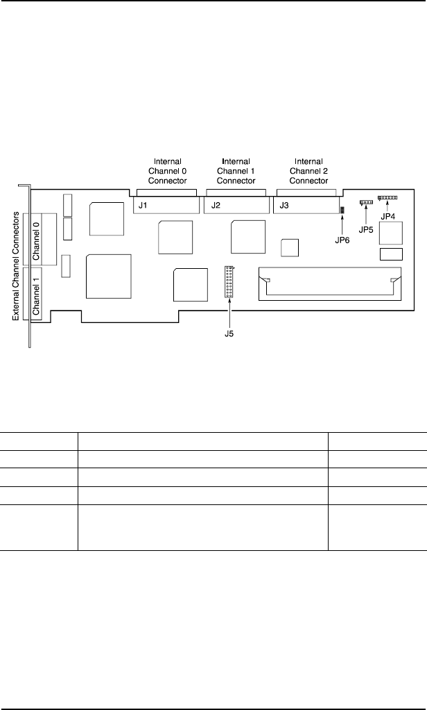
Up to three Ultra SCSI channels are supported on the DAC960PG and
DAC960PJ. The SCSI connector locations are shown in Figure 3-1.
Be sure that the Jumper JP6 has a jumper installed (see Figure 3-1 and
Table 3-1).
Figure 3-1. Full-length Controller Component Layout
Table 3-1. Full-length Controller Jumper and Connector Descriptions
Component Description Default Setting
JP4 Connector for optional front panel LED harness –
JP5 Serial Port Connector –
JP6 Reserved Installed
J5 Battery Backup connector – If a BBU is not
installed, a loopback plug must be installed in
this socket.
Installed at
factory