AcerNote Nuovo User’s Manual
Copyright Copyright © 1996 by Acer Incorporated. All rights reserved. No part of this publication may be reproduced, transmitted, transcribed, stored in a retrieval system, or translated into any language or computer language, in any form or by any means, electronic, mechanical, magnetic, optical, chemical, manual or otherwise, without the prior written permission of Acer Incorporated.
IMPORTANT SAFETY INSTRUCTIONS 1. Read these instructions carefully. Save these instructions for future reference. 2. Follow all warnings and instructions marked on the product. 3. Unplug this product from the wall outlet before cleaning. Do not use liquid cleaners or aerosol cleaners. Use a damp cloth for cleaning. 4. Do not use this product near water. 5. Do not place this product on an unstable cart, stand, or table. The product may fall, causing serious damage to the product. 6.
11. Do not attempt to service this product yourself, as opening or removing covers may expose you to dangerous voltage points or other risks. Refer all servicing to qualified service personnel. 12. Unplug this product from the wall outlet and refer servicing to qualified service personnel under the following conditions: a. When the power cord or plug is damaged or frayed b. If liquid has been spilled into the product c. If the product has been exposed to rain or water d.
Concerning Lithium Batteries ADVARSEL! Lithiumbatteri - Eksplosionsfare ved fejlagtig håndtering. Udskiftning må kun ske med batteri af samme fabrikat og type. Lever det brugte batteri tilbage til leverandøren. ADVARSEL Eksplosjonsfare ved feilaktig skifte av batteri Benytt samme batteritype eller en tilsvarende type anbefalt av apparatfabrikanten. Brukte batterier kasseres i henhold til fabrikantens instruksjoner.
FCC Class B Radio Frequency Interference Statement Note: This equipment has been tested and found to comply with the limits for a Class B digital device, pursuant to Part 15 of FCC Rules. These limits are designed to provide reasonable protection against harmful interference in a residential installation. This equipment generates, uses, and can radiate radio frequency energy and, if not installed and used in accordance with the instructions, may cause harmful interference to radio communications.
About This Manual Purpose This manual discusses the features of the notebook and tells how to use and configure it. Manual Structure This manual consists of eight chapters and two appendices: Chapter 1, Getting Started, tells you how to get started with the notebook. Chapter 2, System Tour, gives a guided and in-depth “tour” of the notebook and its features. Chapter 3, Power, discusses issues on battery use and includes information on the unique power management system.
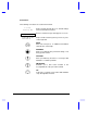
Conventions The following conventions are used in this manual: C:\setup, [Enabled], etc.
Ta b l e o f C o n t e n t s 1 2 Getting Started 1.1 Item Checklist............................................................................................1-2 1.2 Taking Care of Your Computer .................................................................1-3 1.2.1 Notebook ......................................................................................1-3 1.2.2 AC Adapter...................................................................................1-6 1.2.3 Battery Pack .........
2.6 2.7 2.8 2.9 Storage ................................................................................................... 2-20 2.6.1 Hard Disk ................................................................................... 2-20 2.6.2 Module Bay ................................................................................ 2-20 Ports ....................................................................................................... 2-23 2.7.1 Left Panel Ports ............................
3.2 4 Power Management ................................................................................3-10 3.2.1 The Concept of Heuristics..........................................................3-10 3.2.2 Suspend Modes .........................................................................3-11 3.2.3 Advanced Power Management (APM) .......................................3-14 Options 4.1 External Monitor ........................................................................................
5 Software 5.1 System Software....................................................................................... 5-2 5.2 Sleep Manager.......................................................................................... 5-3 5.3 5.2.1 Accessing the Sleep Manager ..................................................... 5-3 5.2.2 Sleep Manager Functions............................................................ 5-5 5.2.3 Running Sleep Manager .................................................
6.4.8 Enhanced IDE Features .............................................................6-11 6.4.9 Onboard Communication Ports..................................................6-12 6.4.10 Onboard Audio ...........................................................................6-15 6.4.11 Reset PnP Resources ................................................................6-16 6.5 6.6 6.7 7 Power Saving Options .............................................................................6-17 6.5.
8 Troubleshooting 8.1 Q & A ........................................................................................................ 8-2 8.2 POST Error Messages.............................................................................. 8-7 A Specifications B Address and Interrupt Tables xiv B.1 System Memory Map ................................................................................B-1 B.2 I/O Address Map...............................................................................
List of Figures 1-1 Write-protecting a 3.5-inch Diskette ..........................................................1-8 2-1 Display.......................................................................................................2-5 2-2 Indicator Lights ..........................................................................................2-7 2-3 Keyboard Layout .......................................................................................2-8 2-4 Palm Rest..........................
L i s t o f Ta b l e s 2-1 Indicator Status Descriptions .................................................................... 2-7 2-2 Lock Key Descriptions .............................................................................. 2-9 2-3 Using the Embedded Keypad ................................................................. 2-10 2-4 Windows 95 Key Descriptions ................................................................ 2-11 2-5 Hot Key List............................................
6-3 Hard Disk Drive Control Settings.............................................................6-24 6-4 Start Up Sequences Settings ..................................................................6-24 8-1 POST Error Messages ..............................................................................
Chapter 1 Getting Started Congratulations on your purchase of the award-winning AcerNote Nuovo notebook computer. Guaranteed and backed by Acer’s world-class support, you can be sure of top-notch performance with your new AcerNote. This chapter guides you through the first few steps on setting up your notebook computer.
1.1 Item Checklist Carefully unpack the carton and remove the contents. If any of the following items is missing or damaged, contact your dealer immediately. • Notebook computer • Accessory box • AC adapter • Battery pack • Floppy drive module • External floppy drive cable • User’s manual and other documentation Check for optional items, if any.
1.2 Taking Care of Your Computer Your computer will serve you well if you take care of it. This section tells you how to care for the notebook. Also, re-read the important safety instructions at the beginning of this manual. 1.2.1 Notebook • • Do not expose the notebook to direct sunlight. Do not place near sources of heat, such as a radiator. Do not expose to temperatures below 0ºC (32ºF) or above 50ºC (122ºF).
• • • • 1-4 Do not subject the notebook to magnetic fields. Do not expose the notebook to rain or moisture. Do not spill water on the notebook. Do not subject the computer to heavy shock and vibration.
• • • Getting Started Do not expose the notebook to dust and dirt. Never place objects on top of the notebook to avoid damaging the notebook. Never place the notebook on uneven surfaces.
1.2.2 AC Adapter The AC adapter provides uninterrupted power to your notebook and charges your battery pack. Here are some ways of taking care of your AC adapter. • • • 1.2.3 Do not connect the adapter to any other device. Do not step on the power cord or place heavy objects on top of it. Carefully route the power cord and any cables away from personal traffic. When unplugging the power cord, pull on the plug and not on the cord itself.
1.2.4 Cleaning and Servicing When cleaning the notebook, follow these steps: 1. Close the display lid to turn the notebook off. 2. Disconnect the AC adapter. 3. Remove the battery pack. 4. Use a soft cloth moistened with water. Do not use liquid or aerosol cleaners. Contact your dealer or see your service technician if any of the following occurs: • Notebook has been dropped or damaged. • Liquid has been spilled into the product. • The notebook does not operate normally. See section 7.
• Write-protect your diskettes to prevent accidental erasure. To do this, slide the write-protect tab to the write-protect position. Write-protected Not write-protected Figure 1-1 • 1-8 Write-protecting a 3.5-inch Diskette When you put a label on a 3.5-inch diskette, make sure that the label is properly attached (flat on the surface) and within the labelling area (area with slight surface depression) on the diskette.
1.3 Connecting the Notebook After reading through the previous section, you are now ready to experience your new notebook. Connecting the notebook is as easy as 1-2-3. Inserting the Battery Pack Insert the battery pack into the battery compartment and slide the battery compartment cover in place. Connecting the AC Adapter Connect one end of the AC adapter to the DC-in port on the notebook’s rear panel and the other end to a properly grounded power outlet.
1.4 Creating Backup and Startup Diskettes Entering User Information When Windows 95 loads for the first time, enter your user information. Have your Windows 95 authentication number ready, found in the Windows 95 documentation package. Creating Backup and Startup Diskettes Windows 95 prompts you to create backup and startup diskettes. If your Windows 95 package contains a Windows 95 CD-ROM, you do not need to create backup diskettes for Windows 95.
1.5 Getting Help Online This user’s manual provides clear and concise information about the notebook, so read it thoroughly. To provide you with help when traveling, the notebook has a comprehensive online help. Accessing Online Help Follow these steps to access the online documentation: 1. Press the Windows logo button or Click on the Start button. 2. Select Programs. 3. Click on AcerNote Nuovo. 4. Select Online Manual. The online help is easy to navigate with hypertext and hypergraphics.
Chapter 2 System Tour This notebook combines high-performance, versatility, multimedia capabilities and a truly advanced power management system in a unique human-centric and stylish design case. Work with unmatched productivity and reliability with your new power computing partner. This chapter gives an in-depth “tour” of the notebook’s many features.
2.1 Features The notebook looks as good inside as it is outside, definitely designed with the user in mind. Here are just a few of the notebook’s many features: Performance • High-end mobile Pentium microprocessor • 64-bit main memory and 256KB external (L2) cache memory • Large display in DualScan STN or active-matrix TFT • PCI local bus video with 128-bit graphics accelerator • Flexible module bay (3.
Human-Centric Design and Ergonomics • Intuitive FlashStart automatic power-on • Sleek, smooth and stylish design • Automatic tilt-up, full-sized, full-function keyboard • Wide and comfortable palm rest • Ergonomically-centered touchpad pointing device Expansion • PC Card (formerly PCMCIA) slots (two type II/I or one type III) • Mini dock option with built-in Ethernet • User-upgradeable memory System Tour 2-3
2.2 Display The large graphics display offers excellent viewing, display quality and desktop performance graphics. The notebook supports two different displays — DualScan STN or active-matrix TFT LCD. Video Performance PCI local bus video with 128-bit graphics acceleration boost your video to desktop-performance level, and allows you to run 30fps full-screen, truecolor video playback via software MPEG.
FlashStart Automatic Power-On A noticeably unique feature about this notebook is that it has no on/off switch. Instead it employs a lid switch, located near the center of the display hinge, that tells the notebook when it should wake up or go to sleep. Lid Switch Figure 2-1 Display When you close the display lid, the notebook enters suspend-to-memory or suspend-to-disk mode before turning off the power, depending on the When Lid is Closed parameter setting in Setup (see section 6.5.1).
The “Lid Closed” State When the lid is closed (i.e., the “lid closed” state), the notebook suspends its normally busy tasks to make itself electronically and mechanically more stable. When the lid is opened, the notebook briefly checks its environment and always re-initializes devices newly added in or removed from the notebook. Though the notebook allows for various hot insertion of peripherals, the “lid closed” state provides the most stable and practical means to attach and detach peripheral components.
2.3 Indicator Lights Two indicator lights are found on the display panel. Power Indicator Battery Indicator Figure 2-2 Indicator Lights These indicators and their descriptions are shown in Table 2-1.
2.4 Keyboard The full-sized keyboard includes an embedded keypad, separate cursor keys, two Windows 95 keys and twelve function keys. Special keys are highlighted in different colors. 2.4.
2.4.2 Special Keys Lock Keys The notebook has the three basic lock keys which you can toggle on and off. as part of a key combination. Some keys may require using Table 2-2 Key # - Lock Key Descriptions Description When Caps Lock is on, all alphabetical characters typed appear in uppercase. When Num Lock is on, the embedded keypad is in numeric mode. The keys function as a numeric keypad like the one found on standard PC keyboards (complete with arithmetic operators +, -, *, and /).
Embedded Keypad The embedded keypad functions like a desktop numeric keypad. It is indicated by small characters located on the upper right corner of the keycaps. To simplify the keyboard legend, the cursor-control key symbols are not printed. Table 2-3 tells how to use the embedded keypad.
Windows 95 Keys The keyboard has two keys that perform Windows 95-specific functions. Table 2-4 Windows 95 Key Descriptions Key Description Windows logo key Start button. Combinations with this key performs special functions.
Hot Keys The notebook uses hot keys (key combinations) to access most of the notebook’s controls like screen contrast and brightness, volume output and the BIOS setup utility. Some hot keys will pop-up a corresponding icon onscreen for better visuals. When activating hot keys, press and hold the first key before pressing the other keys in the combination.
Table 2-5 Hot Key System Tour Hot Key List (continued) Icon Function Description -S Display Toggle Switches display from LCD to CRT to both LCD and CRT -T Fuel Gauge On/Off Toggles battery gauge display on/off. Also shows the following: • “plug” icon if a powered AC adapter is connected to the notebook. • “speaker” icon if speaker output is on (toggled by -U). • “T” icon if turbo mode is on (toggled by - ).
Table 2-5 Hot Key Hot Key List (continued) Icon Function Description - -[ Contrast Up Increases screen contrast (DSTN only) - -] Contrast Down Decreases screen contrast (DSTN only) -Z Fuel Gauge Up With the fuel gauge onscreen, moves the fuel gauge up -\ Fuel Gauge Down With the fuel gauge onscreen, moves the fuel gauge down -] Fuel Gauge Left With the fuel gauge onscreen, moves the fuel gauge left -[ Fuel Gauge Right With the fuel gauge onscreen, moves the fuel gauge right - CD Ej
The eject menu commands allow you to perform various eject-related functions for the notebook. See the following table for details Table 2-6 Eject Menu Descriptions Select… To… Battery Change the battery. This option forces the notebook to enter suspend-to-disk mode, so that you can replace the battery with a charged one, and then return to where you left off. To resume, close the display lid and open the display lid again. CD-ROM Disc Open the CD-ROM drive.
2.4.3 Automatic Tilt Feature The keyboard has the option of automatically tilting to a six-degree angle whenever you open the lid. This automatic tilt feature brings to the notebook the comfortable typing angle provided in standard PC desktop keyboards. Together with the palm rest (discussed in the following section), these two ergonomic features help prevent repetitive strain injury to your wrists and fingers.
3. 2.4.4 Open the lid. Palm Rest Located below the keyboard, the wide and curved palm rest gives you a comfortable place to rest your hands while you type.
2.5 Touchpad The ergonomically-centered touchpad is a pointing device that senses movement on its surface. This means the cursor responds as you move your finger on the surface of the touchpad. Figure 2-5 Touchpad The touchpad works with most mouse drivers. However, the touchpad driver supports special functions that work uniquely with the touchpad. We recommend you use the touchpad driver instead of any other mouse driver.
Touchpad Basics The following two items teach you how to use the touchpad: • • Move your finger across the touchpad to move the cursor. Press the left and right buttons located on the lower edge of the touchpad to do selection and execution functions. These two buttons are similar to the left and right buttons on a mouse. Tapping on the touchpad produces similar results. See Table 2-7.
2.6 Storage 2.6.1 Hard Disk High-capacity storage comes in the form of a 2.5-inch Enhanced-IDE hard disk. The hard disk can be upgraded when you need more storage space. See section 4.9.2 for related information. 2.6.2 Module Bay The notebook’s flexible module bay accommodates either a high-speed CD-ROM drive module or a 3.5-inch, 1.44MB floppy drive. CD-ROM Drive Module Floppy Drive Module Figure 2-6 Module Bay The modules are designed to give you flexibility in the fast-moving portable platform.
Swapping Modules The proper way to cleanly swap or interchange modules is to power off the notebook without the help of any suspend modes. The notebook needs to perform a “cold boot” (Windows 95 shutdown or via the Eject menu) or “warm boot” (Ctrl-Alt-Del) to correctly detect and identify the module currently installed in the module bay. Simply closing the display lid will only put the notebook in either suspend-to-disk or suspend-to-memory. Follow these steps to swap modules: 1. Do a Windows 95 shutdown.
Ejecting a CD To eject a CD, press the eject button - , on the CD-ROM drive, press or use your software to eject the CD-ROM drive. In Windows 95, you can right-click on the CD-ROM drive icon and select the Eject command. Using the Floppy Drive Module Externally You can use the floppy drive module externally when a CD-ROM drive module is installed in the module bay. You cannot use the CD-ROM drive module externally. Only the floppy drive module can be used externally.
2.7 Ports Ports allow you to connect peripheral devices to your notebook computer as you would with a desktop PC. The ports are found on the left and rear panel. The following sections discuss these ports and their functions. See Chapter 4 on how to connect external devices to the notebook. 2.7.1 Left Panel Ports Multimedia ports and the PC card slots are found on the left panel. See Figure 2-7.
Table 2-8 describes these ports. Table 2-8 # Icon Left Panel Port Descriptions Port Connects to... 1 PC Card slots One Type III or two Type I/II PC cards 2 Microphone-in/Line-in External microphone or line input device 3 Speaker-out/Line-out Amplified speakers or headphones PC Card Slots There are two type II/I or one type III PC Card slots found on the left panel of the notebook. These slots accept credit-card-sized cards that enhance the usability and expandability of the notebook.
Ejecting a Card 1. Exit the application using the card. 2. Flip out the slot eject button of the slot where the card is inserted. 3. Press the slot eject button to eject the card. If you want to install a card, refer to your card’s user’s manual for details on how to install and use the card. Multimedia Ports Connecting external audio devices to these ports automatically shuts off the corresponding internal audio device.
2.7.2 Rear Panel Ports The rear panel includes the notebook’s main ports and connectors. See Figure 2-8.
Table 2-9 describes these ports. Table 2-9 # Port Connects to... 1 DC-in port AC adapter and power outlet 2 PS/2 port PS/2-compatible device (e.g., PS/2 keyboard, keypad, mouse) 3 Serial port (UART16650-compatible) Serial device (e.g., serial mouse) 4 Parallel port (EPP/ECP-compliant) Parallel device (e.g.
2.8 Audio Standard notebook configuration includes 16-bit stereo audio with built-in FM synthesizer. Combined with the dual, angled speaker system and built-in sensitive microphone, this notebook redefines portable audio. 2.8.1 Built-in Speakers and Microphone The dual, angled speakers found on both sides of the display hinge directs sound towards you, and its unique audio chamber design allows for better acoustics and sound reverberation resulting in excellent sound quality.
2.8.2 Controlling the Audio There are hot keys that allow you to control various aspects of the audio output.
2.9 Communications 2.9.1 Serial Infrared This notebook has an SIR (serial infrared) port located on the rear panel. Wireless communication support allows you to transfer data to SIR-”aware” machines without the aid of cables. Not only can you transfer data between two SIR-capable computers, you can also send data to SIR-”aware” peripherals like infrared printers without the need to connect cables. The infrared port is IrDA-compliant, allowing it to transfer data with speeds of up to 115.
2.9.2 Fax/Data Modem1 The notebook has an optional state-of-the-art, 28.8Kbps V.34 fax/data modem that supports V.42bis hardware compression (115.2 kilobits per second). The modem also supports DSVD (simultaneous voice over data) technology which allows you to send data and talk at the same time. Using the Modem Connect the phone line cable from the RJ11 modem port on the notebook’s rear panel to the telephone line jack. Begin your communications software program. See your software manual for instructions.
2.10 Securing your Notebook Security features include hardware and software locks — a security notch and a two-level password scheme. 2.10.1 Security Notch A security notch located on the left panel of the notebook lets you connect a standard key-based computer security lock. Circle or wrap a computer security lock cable around an immovable object such as a table or locked drawer handle. Then insert the lock into the notch and turn the key to secure the lock. 2.10.
Chapter 3 Power The notebook operates on AC or battery power. This chapter contains the information you need to know to operate the notebook on battery power. The chapter also includes information about the unique power management system.
3.1 Battery Power The notebook uses a single high-capacity Lithium-Ion smart battery pack that gives you longer use between charges. 3.1.1 Battery Pack Characteristics The battery pack has the following characteristics: • • • Lithium-Ion Technology Lithium-Ion technology does not have the memory effect problem of Nickel Cadmium (NiCd) nor the temperature problem of Nickel Metal-Hydride (NiMH) battery types. Li-Ion batteries consistently provide the longest battery life best-suited for road warriors.
Do not expose battery packs to temperatures below 0ºC (32ºF) or above 60ºC (140ºF). This may adversely affect the battery pack. 3.1.2 Removing and Installing the Battery Pack Removing the Battery Pack Before removing the battery pack, make sure that you have an AC adapter connected to the notebook; otherwise turn off the notebook. The following figure illustrates how to remove the battery pack. 1. Press the battery compartment cover latch and slide it out. 2. Pull out the battery pack.
3.1.3 Charging the Battery To charge the battery, place the battery pack inside the battery compartment and plug the AC adapter into the notebook and an electrical outlet. Charging Modes The adapter has three charging modes: • Rapid charge mode The notebook uses rapid charging when the notebook is in suspend mode and a powered AC adapter is connected to it. In rapid mode, a fully depleted battery gets fully charged in approximately two hours.
3.1.4 Checking the Battery Level There are three ways to check the battery charge level: • Onscreen fuel gauge • Windows 95 battery indicator • Battery pack gauge The fuel gauge shows the minimum guaranteed capacity to provide assurance that the system will be operational for the minimum battery life indicated. Using the Onscreen Fuel Gauge -T. If a powered AC adapter To access the onscreen fuel gauge, press is connected to the notebook, a plug icon also shows in the onscreen fuel gauge.
Using the Battery Pack Gauge The battery pack gauge allows you to check your battery charge level even when it is not installed in the notebook. Press the fuel gauge button on the battery pack to check the battery charge level. Table 3-1 is a battery-level chart.
3.1.5 Optimizing Battery Life Optimizing battery life prolongs the charge/recharge cycle and improves recharge efficiency. Follow these suggestions to optimize and maximize battery power: • • • • • • • • Power Purchase an extra battery pack. Set the When Lid is Closed parameter in Setup to [Suspend to Disk]. See section 6.5.1. Use the AC adapter whenever possible so that the battery is reserved for on-the-go computing. Keep the battery pack in the notebook powered by the AC adapter.
3.1.6 Battery Low Condition You never have to worry about battery power as long as you are using the AC adapter. However, when you operate the notebook on battery power, ). pay extra attention to the battery indicator ( Generally speaking, a battery-low condition occurs when less than twenty percent charge left is in the battery.
Table 3-2 lists the recommended course of action when you encounter a battery-low condition. Table 3-2 Course of Action for Battery-low Condition Situation Recommended Action AC adapter and power outlet available 1. 2. Connect the AC adapter to the notebook to begin charging the battery. Resume work. If you want the battery to recharge faster, close the display or press -_ ( ) to enter suspend mode. An extra fully-charged battery pack available 1. 2. 3. 4. 5.
3.2 Power Management At the very heart of this notebook is a new way of power management called Heuristic Power Management (HPM). Part of the notebook’s overall design, this power management method allows the notebook to provide maximum power conservation and maximum performance. 3.2.1 The Concept of Heuristics Current power management schemes or methods used by notebooks are timer-based. You have to set various time-out values for the display, the hard disk and other devices.
3.2.2 Suspend Modes The heuristic power management system performs automatic suspend, hotkey suspend and all suspend actions resulting from various events and conditions. You only need to set the suspend mode type the notebook enters when a suspend condition occurs. The two suspend modes are: • Suspend-to-memory mode • Suspend-to-disk mode The suspend mode that the notebook enters into is specified in the When Lid is Closed parameter in Setup. See section 6.5.1.
Suspend-to-Memory Mode Conditions For the notebook to enter suspend-to-memory mode, any of the following conditions should exist: • When Lid is Closed parameter is set to [Suspend To Memory] • The suspend-to-disk file is either absent or invalid Entering Suspend-to-Memory Mode With the suspend-to-memory conditions satisfied, there are many ways to enter suspend mode: • Closing the display • Pressing the suspend hot key • Sustained inactivity • Battery fail condition occurs without a powered AC
Suspend-to-Disk Mode In suspend-to-disk mode, power shuts off. The notebook saves all system status information onto the hard disk (in a file created by Sleep Manager) before entering suspend-to-disk mode. The next time you open the notebook, it restores this information from the hard disk and resumes from where you last left off.
3.2.3 Advanced Power Management (APM) This notebook supports the APM standard designed to further reduce power consumption. APM is a power-management approach defined jointly by ® ® Microsoft and Intel . The notebook’s heuristic power management scheme works hand-in-hand with APM to take advantage of power saving features and allows greater system availability without degrading performance. Advanced Power Management greatly prolongs battery life. Use APM whenever possible.
Power 3-15
Chapter 4 Options This notebook offers excellent connectivity and expansion capabilities with its built-in ports and connectors. This chapter describes how to connect 1 peripherals and hardware options to the notebook. When connecting peripherals, read the manual included with the peripheral for operating instructions. This chapter also includes information on the key components that you can upgrade. Key component upgradeability gives you the room to enhance the notebook to meet your future needs.
4.1 External Monitor To show graphical effects on a larger display, you can connect an external ) on the rear panel. Read the monitor manual monitor to the CRT port ( for additional instructions. Figure 4-1 Connecting an External Monitor You can press -S to toggle the display output to the external CRT and back to the notebook display or simultaneously on both displays. If an external monitor is connected to the notebook, the notebook will not enter the desired suspend mode if you close the display.
4.2 External Keyboard This notebook has a keyboard with full-sized keys and an embedded keypad. If you feel more comfortable using a desktop keyboard, you can install a PS/2-compatible external keyboard. To connect an external keyboard, plug the external keyboard into the PS/2 ). connector ( Figure 4-2 Connecting an External Keyboard If you need to connect both external keyboard and PS/2 mouse simultaneously, you can purchase a PS/2 Y-cable from your dealer. See section 4.9.2.
4.3 External Keypad You can also use a 17-key numeric keypad for number-intensive data entry applications. To connect the keypad, plug in the keypad connector to the ) at the rear of the notebook.
4.4 External Pointing Device This notebook accepts either a serial mouse or PS/2-compatible mouse or similar pointing device. Connecting an External Pointing Device If you use a serial mouse, plug it into the serial port ( ) on the rear panel. ) on If you use a PS/2-compatible mouse, plug it into the PS/2 port ( the rear panel. Installing an external PS/2 mouse automatically disables the built-in touchpad.
Setting the External Mouse Location Parameter After connecting the external mouse or similar pointing device, press -P to enter Setup and verify the location of the external pointing device.
4.5 Printer This notebook supports both serial and parallel printers. For a serial printer, ). For a parallel printer, plug the plug the printer cable into a serial port ( printer cable into the parallel port ( ). See your printer manual for operating instructions.
4.6 Audio Devices You can connect audio devices to the line-in and line-out ports on the notebook. The line-in audio port doubles as a microphone-in port as well. The line-in port accepts an external 3.5mm mini-jack microphone or other line-in devices. The line-out port accommodates external amplified speakers or headphones. Figure 4-6 Connecting Audio Devices To use Mic-in or Line in, insert the plug of the desired device and make sure to turn off the appropriate input from the mixer.
4.7 Mini Dock The mini dock serves as a docking base that allows you to connect your notebook to all the peripherals you need, even network connections with its built-in Ethernet support. Consult your dealer for details. A quick guide is included with the mini dock for easy and quick connection instructions. Figure 4-7 4.8 Mini Dock PC Cards The notebook has two PC card slots that accommodate two type I/II or one type III PC card(s).
4.9 Miscellaneous Options 4.9.1 Additional Power Packs Lithium-Ion Battery Pack It is good practice to have a spare battery pack around, especially when you travel. The Li-Ion (lithium-ion) smart battery supplies more power than a conventional NiMH (nickel metal-hydride) battery. With power management, you get even more power on-the-go. Attaching the Battery Compartment Cover Each battery pack comes attached with a battery compartment cover.
Detaching the Battery Compartment Cover Gently pull up the battery compartment cover release latch and slide out the cover. AC Adapter You can purchase an additional AC adapter for your notebook or mini docking station. The compact AC adapter charges your battery pack and supplies power to your notebook.
4.9.2 Cables Floppy Drive Cable The floppy drive cable allows you to use your floppy drive module externally. Open the port cover of the notebook and connect the 25-pin connector end of the floppy drive cable to the parallel port. Then connect the other end to the floppy drive module. PS/2 Y-Bridge Cable The PS/2 Y-bridge cable allows you to connect two PS/2 devices, mouse and keyboard, to your notebook simultaneously.
File Transfer Cable For non SIR- (serial infrared) capable connections, you can use the file transfer cable to transfer data between the notebook and other computers. Connect the file transfer cable between the two computers and use your file transfer utility to perform the transfer.
4.10 Key Component Upgrades This notebook delivers the power and performance you need. However, some users and the applications they use may demand more. This notebook allows you to upgrade key components when you need increased performance. Contact your authorized dealer if you decide to perform an upgrade. 4.10.1 Additional Memory Memory is upgradeable from 8 to 64 MB, employing 64-bit soDIMMs (small outline Dual Inline Memory Modules) in 8, 16 and 32 MB configurations.
Installing Memory When installing memory, we recommend you seek the help of a qualified service technician. Improper installation may damage the memory module or the notebook, or cause a malfunction. One of the two memory slots (Slot 2) is accessible via a memory expansion door on the base of the notebook. Follow these steps to install an additional memory module. Options 1. Press -W to access the eject menu and select the “Hardware Service” option. Press H. 2. Close the display lid. 3.
6. Replace the memory door and secure it with the screws. 7. Open the display to turn on the notebook. After new memory modules have been installed, the system automatically detects and reconfigures the total memory size. To upgrade memory installed in the other slot (Slot 1), contact your dealer. 4.10.2 Hard Disk You can have your hard disk upgraded to one with a higher capacity. The notebook uses a 2.5-inch Enhanced-IDE hard disk that is auto-detected by the system.
Options 4-17
Chapter 5 Software This notebook comes pre-loaded with application software and system utilities. This chapter discusses some of these applications and how to make use of them.
5.
5.2 Sleep Manager Notebooks usually feature built-in power-saving functions. In addition to the normal standby mode for power-saving, our notebooks are also capable of a power management feature called 0-volt suspend to hard disk. When a suspend event occurs, this built-in function saves all the system’s current status onto your hard disk in the form of a file. The system then shuts off the power. When the user resumes (e.g.
The Sleep Manager displays below: Table 5-1 Sleep Manager Window Items Item Description Buttons Click to access the Sleep Manager functions Current Setting Displays the drive and size of the current reserved space created by Sleep Manager. On Board Information Displays the different areas of system memory and their respective values. These system resources need to be stored before the system can enter 0-volt suspend mode, so the system can resume to the previous state successfully.
Table 5-1 Sleep Manager Window Items (continued) Item Description Recommended Size Displays the minimum size of the contiguous space you need for the 0-volt suspend-to-disk feature. The actual size may be a little bit more due to file system alignment. Enable Indicator on the Taskbar When this checkbox is checked, the Sleep Manager status appears on the taskbar.
Sleep Manager automatically checks the system configuration and displays the recommended size. The drive where the space will be created is defined by the system and will be the first available logical drive which has the requested contiguous free disk space on it. The recommended size is the minimum size needed to save the current system status. If the program cannot find the required space on the hard disk during the space creation process, it shows a message box to inform the user.
Another possible reason is that the hard disk has enough free space, but this free space exists as small fragments. The free disk space that Sleep Manager requires needs to be contiguous. To solve this problem, the user can use tools such as SpeedDisk (Norton Utilities) or Disk Defragmenter (Windows 95) to compact these free disk spaces. The user can then run Sleep Manager utility again to reserve the space. Another factor that causes the error is when the user employs disk compression utilities.
Exit The user can exit Sleep Manager by selecting the Exit button. Sleep Manager will then quit and disable the capability of auto-adjusting the reserved space size. Disconnecting this feature is NOT recommended. 5.2.3 Running Sleep Manager Once Sleep Manager is installed on the disk, the system automatically loads this utility every time you start Windows 95. Sleep Manager resides in the background by appearing on the taskbar.
5.2.4 Sleep Manager Troubleshooting Tips The following table lists the error messages you may receive with their corresponding solutions: Table 5-2 5.2.5 Sleep Manager Error Messages and Solutions Error Message Solution BIOS not compliant with Sleep Manager. Sleep Manager can only run on notebooks with a BIOS compatible with this computer. This machine does not have a power management unit. You cannot run Sleep Manager without PMU. Sleep Manager can only work on notebooks installed with a PMU.
To uninstall Sleep Manager from the Windows, follow these steps: 1. Quit the Sleep Manager if it is still running. 2. Click on the Start button and select the Control Panels folder from Settings. 3. Open the Add/Remove Programs Icon. 4. Select the Sleep Manager for Windows 95 and click on Add/Remove.... 5. Follow the screen instructions to complete the uninstallation program.
prior to entering suspend-to-disk mode. Do not deactivate or uninstall Sleep Manager and do not remove or delete the zero-volt suspend/resume file. Otherwise, the function will not work — the notebook will only enter suspend-to-memory mode and not suspend-to-disk mode.
5.3 Touchpad Driver The touchpad works with most mouse drivers, but the touchpad driver supports special functions that work uniquely with the touchpad. The touchpad driver enhances the Mouse dialog box to include these special features. 5.3.1 Configuring the Touchpad Follow these steps to configure the touchpad: 1. Click on the Start button, then select Settings... 2. Select Control Panel to display the Control Panel Window. 3. Double-click on the Mouse icon and select TouchPad.
5.4 XingMPEG The XingMPEG software allows you to play MPEG files on your notebook. Follow these steps to run the XingMPEG player: 1. Click on the Start button. 2. Select Programs. 3. Select the XingMPEG Player folder. 4. Click on XingMPEG Player. Refer to the online help for details on how to use XingMPEG.
5.5 Re-installing System Drivers and Applications The notebook is already configured for optimum performance. Should you need to re-install drivers and applications, these are found in the system utility pack CD in the backup kit. Re-installing System Drivers To re-install drivers under Windows 95, click on Start, Settings, then Control Panel. You can either use the Add New Hardware wizard, or update the driver using the Device Manager (accessing the System icon in Control Panel).
Re-installing System Applications To re-install applications under Windows 95, click on Start, then Run…. Based on the location of the application, run the setup program to install the application.
Chapter 6 Setup The notebook has a BIOS (Basic Input/Output System) setup utility that allows you to configure the notebook and its hardware settings. This chapter tells how to use the Setup utility and describes each parameter item in the setup screens.
6.1 When to Use Setup The notebook is already correctly configured for you and you do not need to run Setup. If you make any changes to the notebook or you receive an Equipment Configuration Error message after you turn on the notebook, you may need to run Setup.
6.2 Entering Setup Press -P to enter Setup. The BIOS Utility main screen displays. BIOS Utility About My Computer System Configuration Power Saving Options System Security Reset to Default Settings ↑↓←→ = Move Highlight Bar, ↵ = Select, Esc = Exit There are five main menu items: • About My Computer • System Configuration • Power Saving Options • System Security • Reset to Default Settings Press Z, \, ] or [ to move from one menu item to another and press H to enter the selected menu.
6.3 About My Computer About My Computer gives you clear-cut information about your notebook PC. The following screen is the first of two pages in this section. About My Computer System Architecture System BIOS System ID Processor Coprocessor Internal Cache (L1) External Cache (L2) Total Memory Bank A Bank B Graphics Controller Display Output Hard Drive 0 Hard Drive 1 Floppy Drive A Floppy Drive B : : : : : : : : : : : : : : : : Page 1/2 MARS 1996-1997 BIOS V2.
About My Computer Expansion Peripherals PCMCIA Slot 0 : PCMCIA Slot 1 : Parallel Port : Serial Port : IrDA : Modem : AC Adapter : Main Battery : Onboard Audio Base Address MPU Base Address IRQ Setting DMA Channel Page 2/2 None None 378h, IRQ7 3F8h, IRQ4 2F8h, IRQ3 3E8h, IRQ 10, 33.6 kbps, V.34, DSVD None 60W Li-Ion : 240h : 300h : IRQ 5 : DMA 0 PgDn/PgUp = Move Screen, Esc = Exit Press ^ to return to the first page.
Table 6-1 About My Computer Item Descriptions (continued) Item Description Internal Cache (L1) Internal cache size and whether it is enabled or not External Cache (L2) External cache size and whether it is enabled or not Total Memory Total memory size Bank A Bank A memory module size, type and speed Bank B Bank B memory module size, type and speed Graphics Controller Graphics controller type Display Output Display type and resolution Hard Drive 0 IDE 0 drive type and size (hard disk) Har
6.4 System Configuration The following screen is the basic system configuration screen. Basic System Configuration Page 1/1 Current Date ---------------- [09/16/96] Current Time ---------------- [16:30:35] Diskette Drive A ------------ [1.44 MB 3.
6.4.2 Diskette Drives The default setting for Diskette Drive A is [1.44 MB 3.5-inch] and refers to the floppy drive whether it is installed in the module bay or connected externally via the parallel port. Diskette Drive B by default is set to [None], and is only enabled if two floppy drives are connected to the notebook. 6.4.3 Hard Disks The Hard Disk 0 parameter is reserved for the hard disk.
For advanced users, the System Configuration section has two hidden pages called Advanced System Configuration that allow you to view and configure more technical aspects of the notebook. The notebook’s BIOS configuration is already tuned for optimum performance and you do not need to access these screens. If you do not fully understand the items in these special screens, do not attempt to change their values.
Press ` again to access the next hidden screen.
6.4.7 External Cache External cache greatly increases system performance by lessening the load of main memory. It is also called L2 (level 2) cache. The default setting is [Enabled]. 6.4.8 Enhanced IDE Features The Enhanced IDE Features section includes four parameters for optimizing hard disk performance. These performance features depend on drive support. Newer drives support most or all of these features. As much as possible, set these parameters to [Auto] (when the option to do so is available).
The highest value, 16 sectors, may not give you the best performance every time, because hard disks behave differently. The default setting, [Auto], allows the system to adjust itself to the optimum read/write setting. Advanced PIO Mode Advanced PIO (Programmed Input/Output) Mode enhances drive performance by optimizing the hard disk timing. The available values include: • Auto • Mode 0 The default setting is [Auto].
Serial Port Base Address This parameter accepts the following values: • [3F8h, IRQ 4] • [2F8h, IRQ 3] • [3E8h, IRQ 4] • [2E8h, IRQ 3] • [Disabled] The default setting is [3F8h, IRQ 4]. IrDA Base Address This parameter accepts the following values: • [2F8h, IRQ 3] • [Disabled] The default setting is [2F8h, IRQ 3]. Modem Base Address and IRQ Setting This parameter accepts the following values: • [3E8h] • [2E8h] • [Disabled] The default setting is [3E8h].
Parallel Port Base Address, Operation Mode and ECP DMA Channel The Parallel Port Base Address parameter accepts the following values: • [378h, IRQ 7] • [3BCh, IRQ 7] • [278h, IRQ 5] • [Disabled] The default setting is [378h, IRQ 7].
6.4.10 Onboard Audio This parameter lets you enable or disable the onboard audio functionality of the notebook. This section also includes settings for onboard audio. The default setting is [Enabled]. Base Address This parameter accepts the following values: • • • • [220h] [230h] [240h] [250h] The default setting is [240h]. MPU Base Address This parameter accepts the following values: • • • • [300h] [310h] [320h] [330h] The default setting is [300h].
6.4.11 Reset PnP Resources The system resources are already properly configured. If resource conflicts should arise, set this parameter to [Yes] to reset the PnP resources and redo allocation. The BIOS automatically sets this to [No ] afterwards. The default setting is [No ].
6.5 Power Saving Options The following screen is the power saving options screen.
6.5.1 When Lid is Closed The notebook’s lid switch acts as its power switch. Simply put, opening the display wakes up the notebook; closing the display puts it to sleep. The When Lid is Closed parameter determines which suspend mode the notebook enters when the display is closed.
6.5.2 Suspend to Disk on Critical Battery With this parameter set to [Enabled], the notebook enters suspend-todisk mode when the battery becomes critically-low. The default setting is [Enabled]. 6.5.3 Display Always On This parameter lets you specify whether the display is always on or not. When enabled, the screen will not blank. The default setting is [Disabled] to save power. 6.5.4 Internal Speaker This parameter lets you turn the internal speaker on and off. The default setting is [Enabled].
6.5.6 Internal Modem For models with an internal modem, set this parameter to [Power-On] when you are using the internal modem. If you are not actively using the internal modem, you can set this parameter to [Power-Off] to conserve power. The default setting is [Power-On]. 6.5.7 Resume On Modem Ring You can set the notebook to resume from suspend-to-memory mode upon detection of a specific number of modem rings, ranging from 1 to 7. Enabling this option overrides the suspend-to-disk function. 6.5.
6.6 System Security The following screen is the system security screen. If a password is currently present, the system prompts you to input the password before entering the System Security screen.
6.6.1 Supervisor and User Passwords The supervisor and user passwords both prevent unauthorized access to the notebook. When these passwords are present, the notebook prompts for the user or supervisor password during system boot-up and resume from suspend. The supervisor password also gives full access to Setup. The user password give limited access to Setup. Setup requires the supervisor password to be set prior to setting the user password.
If you forget your password, you must reset the configuration values stored in CMOS to defaults. Resetting CMOS requires opening up the system unit, so contact your dealer for assistance. Removing a Password If you enter Setup using the user password, you cannot modify or remove the supervisor password. To remove a password, select the desired password to remove and press ] or [. 6.6.2 Diskette Drive Control This parameter allows you to enable or disable the read/write functions of the floppy drive.
6.6.3 Hard Disk Drive Control This parameter allows you to enable or disable the read/write functions of the hard disk. The following table summarizes the available options. Table 6-3 6.6.4 Hard Disk Drive Control Settings Setting Description Normal (default) Hard disk functions normally Write-Protect Disables any hard disk write function. This function protects all sectors only under DOS mode.
6.6.5 Flash New BIOS Contact your authorized dealer if you need to upgrade your BIOS.
6.7 Reset to Default Settings Selecting this option allows you to load all the default settings. These settings are the values initially stored in CMOS RAM intended to provide high performance. If in the future you change these settings, you can load the default settings again by selecting this option. When you select this option, the following prompt appears: Reset to Default Settings Are you sure? [Yes] [No] Select [Yes] to load the default settings or [No] to abort the operation.
Chapter 7 Traveling with the Notebook This chapter tells you what to do when traveling with the notebook. This chapter also includes a list of our worldwide offices and contact information.
7.1 Travel Preparations Follow these steps to prepare the notebook for travel: 1. Make diskette or tape backup copies of important files on the hard disk. 2. Close the display to turn off the notebook and all peripherals. 3. Make sure the display is properly closed. The display cover latch must be secure. 4. Disconnect the AC adapter and all peripherals. 5.
7.2 International Traveler’s Warranty Your notebook is backed by an international warranty that gives you security and peace of mind when traveling. Our worldwide network of certified service centers are there to give you a helping hand. Refer to the ITW information hand-out.
7.3 Worldwide Support With your purchase of an AcerNote comes the guarantee of support from our offices worldwide. Have your ITW (international traveler’s warranty) card number ready when you call. World Headquarters Worldwide Operations Acer Incorporated 156 Min Sheng E. Road Sec. 3, 6F Taipei, Taiwan 105, R.O.C. Telephone: 886-2-545-5288 Facsimile: 886-2-545-5308 WWW: http://www.acer.com.
Acer Korea Co. Ltd. DaeYoung Building, #831 44-1 Yoido-Dong, YoungDeungPo-Ku Seoul, South Korea Telephone: 82-2-784-6898/9 Facsimile: 82-2-784-6897 Acer Market Services, Ltd. Science & Technology Trade Center 4th Area, 3F Rm.329 37 Bai Shi Qiao Rd., Haidian District, Beijing, People’s Republic of China Telephone: 86-1-847-2233 Facsimile: 86-1-847-1101 Acer Sales & Services Sdn. Bhd.
New Zealand Acer Computer New Zealand Ltd. AcerHouse, Level 7 10-12 Scotia Pl. Auckland, New Zealand Telephone: 64-9-302 8500 Facsimile: 64-9-302 8501 Europe Acer Belgium N.V. Coremansstraat 34, 2600 Antwerpen (Berchem) Belgium Telephone: 32-3-2305032 Facsimile: 32-3-2813325 Acer Computer B. V. Europalaan 89 5232 BC’s-Hertogenbosch The Netherlands Telephone: 31-73-6459645 Facsimile: 31-73-6459699 Acer Computer France S.A.R.L. Paris Nord II 165 avenue du Bois de la Pie B.P.
North America Sales Offices Acer America/Boston Burlington Office Park 1 Wall St. Burlington, MA 01803, USA Telephone: 1 (617) 272-2572 Facsimile: 1 (617) 272-5155 Acer America/Canada 9-5155 Spectrum Way Mississauga, Ontario L4W 5A1, Canada Telephone: 1 (905) 602-8200 Facsimile: 1 (905) 602-7799 Acer America/North Central West Two Continental Towers 1701 Golf Rd.
Latin America Acer Latin America 1601 NW 84th Avenue Miami, FL 33126, USA Telephone: 1 (305) 477-8119 Facsimile: 1 (305) 477-5963 Sales Offices Acer Argentina Marcos Sastre 3620, Carapachay Buenos Aires, Argentina 1605 Telephone: 541-763-1111 Facsimile: 541-763-0222 Acer Chile Antonio Varas 754, Casilla 972 Santiago de Chile, Chile Telephone: 562-200-9301 Facsimile: 562-200-9310 Acer Computer Colombia Cra 129 #29-57 Bodega No.
Chapter 8 Troubleshooting This chapter tells how to deal with common system problems. Read it before calling a technician if a problem occurs. Solutions to more serious problems require opening up the system. Do not attempt to open the system by yourself. Contact your dealer or an authorized service center for assistance.
8.1 Q&A Q & A lists possible situations that may arise during the use of your notebook, and gives easy answers and solutions to these questions. Q: I travel a lot and occasionally use my notebook in extreme temperature conditions. Will my notebook bend to the weather? A: The notebook’s core design makes use of materials that dissipate heat quickly, without the need of a fan that can be noisy at times.
Q: I prefer using an external keyboard and mouse, but both have PS/2 connectors and there is only one PS/2 port on the notebook. How do I connect them to the notebook at the same time? A: To connect two PS/2-type devices to the notebook, you need to use a PS/2 Y-bridge cable. See PS/2 Y-Bridge Cable in section 4.8.2 for details. Connecting two PS/2-type devices via the mini dock is not a problem, because there are separate PS/2 connectors for an external keyboard and mouse.
Q: I made some changes in Setup but they don’t seem to take effect. A: If you made any changes in Setup, these will only take effect the next time the system restarts. Here a few ways to restart your notebook: • In Windows 95, click on the Start button and select Shutdown…. Then select the Restart option. • In POST, execute a warm boot (pressing E-D-F). • In POST, close the display and open the display. • Use the reset notch. See Q&A #2. Q: Nothing appears on the screen.
Q: The serial mouse does not work. A: Do the following: • Make sure that the serial cable is plugged securely into the serial port. • Try pressing -Q (PnP) to reconfigure Plug-and-Play devices. Remember to set the External Mouse Location parameter in the Power Saving Options screen in Setup and select COM1 if you connected your mouse to the serial port. Q: The printer does not work. A: Do the following: • Make sure that the printer is connected to a power outlet and it is turned on.
Q: No audio comes out from the notebook. A: Check the following: • The volume may be muted. Press ). If the pop-up -T ( ) to turn the does not contain a speaker icon, press -U ( speaker back on. • The volume level may be too low. increase the volume. • If headphones, earphones or external speakers are connected to the headphone/speaker-out port on the notebook’s left panel, the internal speakers automatically turn off. • Onboard audio may be disabled.
8.2 POST Error Messages If you receive an error message during POST, note the message and take corrective action. Table 8-1 lists the error messages in alphabetical order together with the recommended course of action. Table 8-1 POST Error Messages Error Message Corrective Action CMOS Battery Bad Contact your dealer or an authorized service center. CMOS Checksum Error Contact your dealer or an authorized service center. Disk Boot Failure Insert a system disk in drive A, then press H.
Table 8-1 POST Error Messages (continued) Error Message Corrective Action Missing operating system Correct the HDD type and reboot. See the specification label pasted on the back side of the notebook or attached to hard disk drive. We suggest you set the HDD type to [Auto] for hard disk drive auto-detection. Non-system disk or disk error. Replace and strike any key when ready Insert a system disk in drive A, then press H. Pointing Device Error Contact your dealer or an authorized service center.
Troubleshooting 8-9
Appendix A Specifications Item Standard Microprocessor Mobile Intel Pentium™ processor (133/150MHz) Memory System / Main External cache Optional 16MB Dual 64-bit memory banks Expandable to 64MB using 8/16/32MB soDIMMs 256KB L2 cache (synchronous SRAM) 512KB L2 cache FLASH BIOS 256KB Storage system One 2.5-inch, high-capacity Enhanced-IDE hard disk Higher-capacity E-IDE hard disk One high-speed IDE CD-ROM drive module One 3.5-inch, 1.
Item Standard Audio system 16-bit stereo audio with built-in FM synthesizer Optional Built-in microphone and dual angled speakers Communications system1 Built-in V.34 fax/data modem (28.8Kbps) with digital simultaneous voice over data (DSVD) support PC card modem Operating system Windows 95 DOS and Windows 3.
Item Standard Optional I/O ports (continued) One type III or two type II PC Card slot(s) LAN card or other PC cards One serial infrared port (IrDA-compliant) External IR adapter One 3.5mm minijack microphone-in/line-in port Microphone or line-in device One 3.5mm minijack speaker-out/line-out port Speakers or headphones RJ11 phone jack1 1 Weight with FDD with CD-ROM (includes battery) 3.4 kg. (7.4 lbs.) 3.5 kg. (7.7 lbs.
Item Standard Optional AC adapter 100~240Vac, 50~60Hz autosensing AC adapter Extra AC adapter Battery pack Type Charge time A-4 Extra battery pack 57WH Lithium-Ion battery with intelligent charging and built-in battery gauge 2.0-hour rapid-charge 4.
Appendix B Address and Interrupt Tables B.
B.
B.3 B.