ACS-77100 RAID controller User Manual
User’s Manual Preface ..........................................................................................................................3 Notice......................................................................................................................3 Trademarks ..............................................................................................................3 About This document................................................................................................
User’s Manual 5.1. Firmware updating steps .................................................................................. 23 6. Trouble Shooting ....................................................................................................... 26 7. FAQ.......................................................................................................................... 27 8. Contact Accusys ........................................................................................................
User’s Manual Preface Notice Product features and specifications described in this manual are subject to change without notice. The manufacturer shall not be liable for any damage, or for the loss of information resulting from the performance or use of the information contained herein. Trademarks Accusys and the names of Accusys products and logos referenced herein are trademarks and/or service marks or registered trademarks and/or service marks of Accusys, Inc.
User’s Manual About This document This document discusses how to properly design your RAID solution when using the ACS-77100 RAID controller, and guides you to configure the RAID controller. Customer should have a working knowledge of RAID planning and data storage.
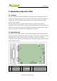
User’s Manual 1. Introduction to the ACS-77100 1.1. Overview The ACS-77100 RAID controller provides RAID 0 (striping), RAID 10 (Striping and mirroring) and RAID 5 (striping with parity) for you to construct a disk array optimized for performance or reliability. By connecting the SATA cables between the ACS-77100 and the disks, a RAID solution can be easily built.
User’s Manual 1.3. Understanding RAID Levels 1.3.1. RAID 0 (striping) RAID 0 links each drive in the array to from one large drive. Storage capacity is determined by the smallest drive in the array. This capacity is then applied to format all other drive in the array. When using a 40GB, 50GB and a 60GB drive in a RAID 0 array, your system will have, in effect, one 120GB drive (40GB x 3) The diagram above represents the writing of data on a RAID 0 array composed of four disks connected to the controller.
User’s Manual 1.3.2. RAID 10 (striping and mirroring) RAID 0+1 combines mirroring and striping functions on a minimum of four hard disks. Mirroring provides full redundancy and protects data in case of multiple drive failure (providing that data on one of each mirrored pair of drives is intact). The diagram shown represents the writing of data on a RAID 0+1 array composed of four DISKS connected to the controller.
User’s Manual 1.3.3. RAID 5 (striping with parity) and RAID 5+hot spare RAID 5 uses a mathematical expression that compares data from three drives and calculates a fourth piece of data called “parity” which is saved on a fourth drive. Should one of the drives failed, parity data can be used to rebuild the failed data. Under RAID 5, parity data is stored across all drives in the array. This maximizes the amount of storage capacity available from all drives in the array while still providing data redundancy.
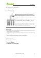
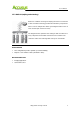
User’s Manual 2. Build a RAID Solution This chapter covers the installation of the ACS-77100. The customers will be guided to using ACS-77100 to build a RAID solution. 2.1. Hardware Requirement: ACS-77100 RAID controller Backplane or Disk I/O board Disk carriers (with LED Indicators) Power supply Fan module Chassis Other materials SATA disk cable Header to DB9 cable SATA to eSATA internal cable Selector (with header connector + cable) http://www.accusys.com.
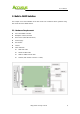
User’s Manual 2.2. LCD Panel Operations The LCD messages are displayed on the screen of LCD panel for system status. Access LED ▲: Scroll up button Power LED ▼: Scroll down button ENT: Enter button ESC: ESC button Scroll up button: to scroll up message data. Scroll down button: to scroll down message data. Enter button: to confirm or enter your selection. ESC button: back to the top layer of message data. http://www.accusys.com.
User’s Manual 3. Set up the RAID solution This chapter covers the configuration of the ACS-77100. Through an easy process, the customers will be guided to configure the ACS-77100 through the following steps: Step 1 3.1. Setting the RAID level – The ACS-77100 is per-configured at RAID level 5, but you have the option of customizing your RAID level in this step Step 2 3.2. Creating an Array – The disks in ACS-77100 will be used to create an array, by which you can partition and use the storage.
User’s Manual 3.1.1 RAID Level configurations RAID Level 5 RAID Level 0 Pin1-3 is open. Pin1-3 is short. Pin5-7 is open. Pin5-7 is short. RAID Level 10 RAID Level 5 + spare Pin1-3 is short. Pin1-3 is open. Pin5-7 is open. Pin5-7 is short. Note If the RAID level is not matched between the disk setting and the RAID level selector setting, the LCD will display the following two messages alternatively: (1) “RAID level” “Unmatched” (2) “Current: R(X)” (i.e.
User’s Manual 3.2. Creating an Array 3.2.1 Enable/Disable Over 2TB capacity ACS-77100 supports over 2TB capacity. The steps below will guide you to enable/disable over 2TB capacity. 1. Select scroll button to find the capacity setting item on LCD panel. (P.18, 4.1.2. Set over 2TB capacity Messages ) 2. Press the ENT button, and select (YES) or (NO) by the scroll buttons. Note If you want to create the array with over 2TB capacity, the setting must be finished before to create an array. 3.
User’s Manual Note The device over 2TB capacity should be supported by Operation System (e.g. Windows Vista). Please refer to section 3.5. Formatting and Partitioning the ACS-77100 to partition the device. 3.3. Setting the Time and Date by LCD To change the time and date on the LCD, press and hold the ENT button for five seconds. Release the button to display the date and time setting screen. To adjust the time and date values, use the Scroll buttons to change the values. (Figure 3.3.
User’s Manual 3.4. Connecting ACS-77100 to the Host computer 1. Follow the steps on page 11, 3.1. Setting the RAID Level and 13, 3.2. Create an Array to establish a RAID. 2. Connect an end of the eSATA cable into the eSATA port on the ACS-77100 RAID subsystem. 3. Connect the other end of the eSATA cable into the eSATA port on the host computer. It will take a few seconds for the host computer to recognize the drive for it to appear in My Computer or on the desktop.
User’s Manual 4. Windows operation system will list all the hard drives that are installed on the system. Locate the ACS-77100 drive that is represented by the icon. Right click the icon and select Initialize. 5. In the drive box to the right shows Unallocated, right click and select New Partition. (Figure 3.5.1.B) 6. The New Partition Wizard dialog box will appear, click Next to continue. (Figure 3.5.1.C) 7.
User’s Manual 3.5.2. Formatting drive over 2TB capacity on Windows Vista The steps below will guide you to format a drive over 2TB capacity on Window Vista. 1. Right click Computer and click Manage. 2. From the Computer Management window, select Disk Management. 3. Windows operation system will list all the hard drives that are installed on the system. Locate the ACS-77100 drive that is represented by the icon. Right click the icon and select Initialize Disk. 4.
User’s Manual 4. Management 4.1. LCD displayed Messages The status of the ACS-77100 can be viewed through the LCD display. By using the scroll buttons to scroll through the messages, the following information is available. RAID level and capacity Disk drive model Disk capacity Controller firmware version Controller serial number Fan and temperature status 4.1.1.
User’s Manual 4.1.3. Initialization Messages LCD Display Create New RAID? No (Yes) RAID INIT XX.X % Total: XXXX GB RAID Init 100 % XXXX GB INIT OK! Message Create a new RAID. New array being created. RAID Initialization completed successfully. LCD Display RAID INIT Failed DX offline RAID INIT Failed DX Bad sectors Message Disk X failed during the initialization. The initialization cannot proceed. Too many bad sectors in Disk X, initialization cannot proceed. 4.1.4.
User’s Manual 4.1.5. Rebuild Messages LCD Display DX Rebuild XX.X% Total: XXX GB DX Rebuild 100% XXX GB OK! DX Rebuild Fail XX GB < YYY GB DX Rebuild Fail DX offline DX Rebuild Fail DX Bad sectors Message Rebuilding data to a new disk (Disk X) since Disk X failure. Disk rebuild completed successfully. The capacity of the new disk (Disk X) is too small. XXX GB is the capacity of the new disk. YYY GB is the minimum disk capacity of the RAID. Disk rebuilding fail since Disk X failed.
User’s Manual Disk Failure Message LCD Display Message Disk X fail Disk X failed. Fan Failure Message LCD Display Fan Fail XXXX rpm Message Fan failure. The xxxx rpm is the current rpm for the fan. Overheating Error Message LCD Display Message Temperature!! XX°C > 50°C System overheating. The XX is the current temperature 4.2. StorConn GUI introduction ACS-77100 support remote RAID subsystem monitoring by web-based GUI. This section covers the introduction of the monitoring software.
User’s Manual 4.2.1. RAID status monitoring window 1. RAID controller tab: Allow customer to select which RAID to monitor. 2. Controller information: Lists model name, serial number and current RAID level. 3. Disk status: Allows you to monitor the status of each of the disk drives. 4. Disk information: Lists model name and capacity of each of the disk drives. 5. Re-build / initialize progress: Tracks the re-building or initialization process. http://www.accusys.com.
User’s Manual 5. Update Firmware ACS-77100 allows the customers to update firmware via RS-232 interface. The firmware can be updated from a host PC with third party communication software, such as HyperTerminal, that supports ANSI terminal emulation. The setup process for HyperTerminal will be guided in this chapter. Note The data and configurations on the array are not affected by firmware updating. Note The HyperTerminal is bundled as standard with Microsoft Windows operating system.
User’s Manual 4. Select COM1 or COM2 from the Connect using: dropdown menu, depending on which port is connecter to ACS-77100. 5. The COM properties dialog box will appear. Set the following values: Bit per second: 19200 Data bits: 8 Parity: None Stop bits: 1 Flow Control: Xon/Xoff 6. Turn on the ACS-77100 and press the ESC button on the host computer keyboard. The “>>>” prompt will appear. http://www.accusys.com.
User’s Manual 7. Type in the command “download” to go to the firmware download mode, then type “1” to download code (Firmware or Bootcode). >>> download restart … 01 GPIO 01 AAA 01 01 ========= 76 Download Mode ========= Enter ‘1’ to Download Code (Firmware, Bootcode) ‘ESC’ exit ‘r’ reset --------------------------- version: Boot ---- 13 (a) ---- 03 Downloading Code! Flash type: SST39VF040 8. Locate the updates firmware file to send.
User’s Manual 6. Trouble Shooting Problem Possible solution The ACS-77100 does Ensure that the array has completed the initialization process. not appear in the BIOS. How should I react to For a RAID 5/RAID 10 array, you should replace the failed disk. disk failure? Data rebuilding will then begin. For a RAID 5+hot spare array, data will be rebuilt automatically to the hot-spare disk. There is no need to immediately replace the failed drive.
User’s Manual 7. FAQ If you encounter a problem while using the RAID box, check this section for help. 1. I have connected the ACS-77100 to host computer, but the host computer cannot recognize the ACS-77100 in BIOS. The array of the ACS-77100 must be created so that the host computer can recognize the RAID in BIOS. Please make sure that an array is created. 2. My Operating System is Linux. I have enabled the over 2TB capacity setting, but I still cannot partition a device over 2TB in OS.
User’s Manual 8. Contact Accusys Accusys, Inc. • 8F, No. 47, Lane 2, Sec. 2, Guangfu Rd., Hsinchu, Taiwan • Tel : +886-3-575-0668 • Fax : +886-3-575-0866 • Website: www.accusys.com.tw • Sales : sales@accusys.com.tw • Support: support@accusys.com.tw Accusys U.S.A., Inc. • 46710 Fremont Blvd. Fremont, CA 94538, U.S.A. • Tel:+1-510-661-0800 • Fax:+1-510-661-9800 • Toll-free number:+1-866-277-5888 • Website: www.accusysusa.com • Sales : sales@accusysusa.
User’s Manual Accusys EU B.V • Columbusstraat 22-26, Distripark Eemhaven, 3165 AD Rotterdam, Netherlands • Tel : +31-10-4284117 • Fax : +31-10-4284114 • Website: www.accusyseu.com • Sales : sales@accusyseu.com • Support: support@accusyseu.com Accusys Korea, Inc. • Baegang B/D 5F Shinsa-Dong 666-14 Kanggnam-Gu, Seoul, Korea • Tel : (02)6245-9050 • Fax : (02)3443-9050 • Website: www.accusys.co.kr • Email : sales@accusys.co.kr http://www.accusys.com.