
Instruction manual


26
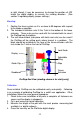
8. Plug the readhead into the display. Move the assembly from left to
right and note if the display's readings increase or decrease.
Depending upon the installation, it may be necessary to change JP3
inside the digital display to reverse the reading direction. (See
section 3 regarding display jumper settings.)
9. After the Measurement Table Kit has been assembled, it is very
important to check that the scale will be mounted in the exact
direction of the desired measurement, as measuring errors will
result if the scale is not properly aligned. See "Abbe error" on page
57 for more information.
10. Mount the scale using M4 (or #6) Flathead screws. Check that the
backstop is solid and will not move under pressure. The scale may
be recessed if desired; the cutout for the scale should be at least
2.02 inches wide for the full length of the aluminum scale.
Maintenance:
The digital scale should be cleaned of all debris often. This will prevent
premature damage to the scale or readhead. Should the assembly
become difficult to move, check that the scale is thoroughly cleaned.
Find, and remove any burrs which may have developed on the aluminum
scale. Do not use any liquid lubricants on the scale assembly, as this
may:
1. Impede the readhead's ability to operate properly.
2. Attract other contaminants to the scale.
3. Swell the black bearings on the moving assembly, thus making the
assembly tighter on the scale.
The Digital Display should be cleaned periodically with compressed air to
remove any dust on the lens and keys. All fasteners should be checked
occasionally for tightness. If there is any wear on the green laminate of
the scale, the guide clip pressure on the readhead should be lessened.
If wear continues, the readhead bearing should be replaced.
NOTE:
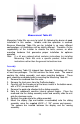
Completely assembled measurement systems are also available from
Accurate Technology
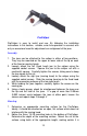
ProTable I Single Axis Measurements
ProTable II Two Axis Measurements
ProTable III Three Axis Coordinate
Measurements
ProTable I