
Instruction manual


22
or right infeed), it may be necessary to change the position of JP3
inside the digital display to reverse the reading direction. (See
section 3 regarding display jumper settings.)
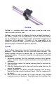
Mounting:
1. Position the fence system so it is as close to 90 degrees with respect
to the blade as possible.
2. The included installation nuts fit the T-slot in the bottom of the fence
extrusion. These nuts can be used with the included bolts to mount
the ProStop from the bottom.
3. The anti-tearout block (oak piece with bolts and nuts) can be used if
the ProStop will be cutting parts where tearout is a problem. The
block should be installed on the face of the fence extrusion, with the
nuts inside the T-slot on the front of ProStop.
Calibration:
Once installed, ProStop can be calibrated easily and quickly. Following
is an example of calibrating ProStop for a cutoff saw application. Other
installations follow the same general procedure.
1. Check to be sure installation of all parts is complete, all fasteners are
secure and the display is plugged in.
2. Cut a part using the normal operation.
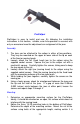
3. Measure the length of the part with the most precise measuring tool
available (i.e. digital calipers).
4. Press the zero key on the ProScale digital display.
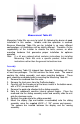
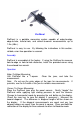
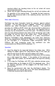
ProStop End View (shading shown is for clarity only)
Stop
Lock Knob
Display
Guide Clip
Readhead
Fence
Extrusion
Adjustable
Wing