ProScale™ General Instruction Manual Includes: ProScale Model 150 & 250 ProStop Measurement Table Kits ProPanel ProCaliper Digital Displays Accurate Technology, Inc. 270 Rutledge Rd. Unit E Fletcher, NC 28732 USA 800 233-0580 • 828-654-7920 Fax 828-654-8824 www.proscale.com info@accurate-technology.
Warranty Accurate Technology, Inc., warrants this product against defective parts and workmanship commencing from the date of original purchase. Upon notification of a defect, Accurate Technology, Inc., shall have the option to repair or replace any defective part. Such services shall be the customer's sole and exclusive remedy. Expenses incidental to repair, maintenance, or replacement under warranty, including those for labor and material, shall be borne by Accurate Technology, Inc.
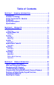
Table of Contents SECTION 1 GENERAL INFORMATION ........................................... 5 Introduction ...................................................................................5 ProScale Technology ....................................................................6 Scales-Incremental Vs. Absolute...................................................7 Readheads ....................................................................................9 System Descriptions ............................
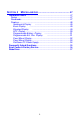
SECTION 4 MISCELLANEOUS ........................................... 47 Installation Notes ........................................................................47 Scales .......................................................................................47 Readheads ................................................................................47 Displays ....................................................................................48 Incremental Display .......................................
SECTION 1 GENERAL INFORMATION Introduction ProScale™ digital measuring systems are high-precision electronic devices for making linear measurements with speed and accuracy, consisting of a scale, a readhead (or encoder) mechanism and a digital display unit. ProScale uses patented capacitive encoder technology, the same technology used in high accuracy digital calipers. ProScale is compatible with most machines used to dimension wood, metal, plastic or composite materials.
ProScale Technology All ProScale systems consist of a SCALE, READHEAD, and a DISPLAY. The SCALE consists of a series of conductive patterns on a nonconductive substrate. The READHEAD contains a computer chip which transmits and receives signals to the scale using capacitive coupling (without actually touching the scale). The received signal is used by the computer chip to calculate the READHEAD position to 0.01mm precision.
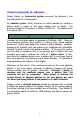
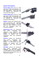
Scales-Incremental Vs. Absolute Simply stated, an Incremental system measures the distance it has traveled relative to a starting point. An absolute system (ABS) measures its actual position by reading a pattern which is unique at any given location over its length. The maximum length of this pattern is 430mm (16.932 in.). The pattern must then repeat itself. Consider the illustration above to represent a ProScale ABS.
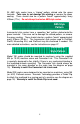
All ABS style scales have a “zigzag” pattern etched onto the green laminate. Take care to not damage this etching or remove the green coating. There should also be a pattern “break” approximately every 430mm (17in.). Do not attempt to shorten ABS style scales. ABS Style Pattern Incremental style scales have a repeating “bar” pattern etched onto the green laminate. Take care not to damage the etched pattern, or remove the green coating. There should also be a pattern “break” approximately every 575mm (22.
Readheads ABS style readheads have “BLACK END OF SCALE” labels on the cover, and the telephone-style wire exits from the corner of the housing. Extreme care must be taken not to damage the six brass “fingers” inside the readhead housing. ABS style readheads, used in all Model 150 and Model 250 systems, must be mounted on ABS scales with a particular orientation.
System Descriptions ProScale Model 150 systems use ABS style scales, ABS style readheads, and ABS style displays. Neither the scale nor readhead are compatible with Incremental style displays. ProScale Model 250 systems use ABS style scales, ABS style readheads, and ABS style displays. Neither the scale nor readhead are compatible with Incremental style displays. ProStop systems use Incremental style scales, Incremental style readheads, and ABS style displays.
Other Accurate Technology System Descriptions (See individual product manuals for detailed descriptions & operation for the products below) ProKits use Incremental style scales, Incremental style readheads, and ABS style displays. The ABS displays have been modified to operate with the Incremental scale and Incremental readhead. See the installation and operation manual for your ProKit for more information. ProSet uses ABS style scales, ABS style readheads, and special displays.
Specifications Accuracy: ± .165mm per meter to ± .2mm max. error ± .002in per foot to ± .008in max. error Repeatability: 0.01mm or .001in. Max. Slew Rate: Model 150: Model 250: ProStop: ProKits: Measuring Kits: ProPanel: ProCaliper: 450 mm/sec. (18 inches/sec.) 450 mm/sec. (18 inches/sec.) 600 mm/sec. (24 inches/sec.) 600 mm/sec. (24 inches/sec.) 600 mm/sec. (24 inches/sec.) 600 mm/sec. (24 inches/sec.) 600 mm/sec. (24 inches/sec.) Display Range: ± 9999.99 mm, ± 394.
ProPanel: ProCaliper: Two years from date of purchase Two years from date of purchase Operating Temperature: 0 to 51°C/ 32 to 120°F Output Format: SPC display: Mitutoyo SPC format. ProScale may be connected to a computer or data logger. Call Accurate Technology, Inc. for more information. Cable: Six-conductor, terminated by RJ12 modular connector. To increase or decrease cable length, contact Accurate Technology. Dimensions: All product dimensions available upon request.
SECTION 2 PRODUCTS ProScale Model 150 ProScale Model 150 systems are general purpose absolute measuring systems designed for taking measurements less than 450mm (18in.). ProScale is easy to install. By following the basics of good installation in this section, reliable, error-free operation is assured. Because ProScale can be installed on many different types and brands of equipment, all installations will be a little different.
4. 5. 6. DISPLAY MOVING PART OF MACHINE CONNECTOR LINK READHEAD A Typical Model 150 Installation 15 MOVEMENT 3. The Display should be mounted in a location which allows for easy viewing by the machine operator. The location of the parts should also safeguard the cable from possible damage. All ProScale wiring should be kept as far away as possible from the machine’s wiring and motors and dust collection systems. Avoid running the readhead wiring parallel to high voltage/current wiring.
Calibration: Once installed, ProScale can be calibrated easily and quickly. Following is an example for calibrating ProScale on an industrial sander. Other installations follow the same general procedure. 1. Check to be sure installation of all parts is complete, all fasteners are secure, and the display is plugged in. 2. Set the machine to sand as normal. Using the regular operation, run a part through the sander. 3.
ProScale Model 250 ProScale Model 250 systems are general purpose absolute measuring systems designed for taking measurements up 6.0m (236in.). ProScale is easy to install. By following the basics of good installation in this section, reliable, error-free operation is assured. Because ProScale can be installed on many different types and brands of equipment, all installations will be a little different.
3. Mount the scale using M4 (or #6) screws. It may be necessary to use washers or spacers to ensure a good mount if the scale is to be mounted on an uneven surface. Be sure the screw heads do not protrude above the surface of the extrusion. If they do, they will interfere with the readhead. a. Check that the scale is properly aligned with the direction of motion of the moving part (any error in alignment will be magnified by the digital components, and could cause premature failure).
5. Reinstall the readhead if it has been removed from the scale. Care should be taken to not damage the readhead’s sensitive internal ground fingers. Also note the orientation label on the readhead housing. Carefully slide the readhead onto the scale, checking for the proper orientation. 6. Slide the readhead until it meets and engages with the guide clip. Check that the guide clip exerts sufficient pressure on the readhead, as seen in the figure below. Guide Clip Readhead 21.2mm (.83") 33.0mm (1.
3. Measure the length of the part with the most precise measuring tool available (i.e. digital calipers). 4. Press the zero key on the ProScale digital display. Note: If the direction of movement and the direction shown on the digital display are opposite, the position of internal jumper JP3 should be changed. See Section 3 for more information. 5. Press and hold the PLUS key to scroll until the length measurement is displayed (the longer the PLUS key is held down, the faster the display will scroll). 6.
ProStop ProStop is a complete digital stop and fence system for chop saws, radial arm saws, and miter saws. ProStop is easy to install. By following the basics of good installation in this section, reliable, error-free operation is assured. Because ProStop can be installed on so many different types and brands of equipment, all installations will be different.
or right infeed), it may be necessary to change the position of JP3 inside the digital display to reverse the reading direction. (See section 3 regarding display jumper settings.) Mounting: 1. Position the fence system so it is as close to 90 degrees with respect to the blade as possible. 2. The included installation nuts fit the T-slot in the bottom of the fence extrusion. These nuts can be used with the included bolts to mount the ProStop from the bottom. 3.
5. Press and hold the PLUS key to scroll until the measurement is displayed (the longer the PLUS key is held down, the faster the display will scroll). 6. When the proper reading is reached, lock the display if desired. This prevents accidentally re-zeroing of the display. See Section 3 for more information about how to lock the display. 7. Re-calibrate, if necessary, after changing saw blades (or applicable tooling). 8. Calibration is also necessary after display batteries are changed. Maintenance: 1.
ProKits ProKits are easy to install. By following the basics of good installation, reliable, error-free operation is assured. Because individual machines may have different manufacturing dates and/or castings, some installations may differ, and require hardware not provided by Accurate Technology. In these cases, it's the responsibility of the installer to choose the additional bolts, screws, or other mounting hardware that guarantee proper installation and optimum operation.
Measurement Table Kit Measuring Table Kits are easy to install. By following the basics of good installation in this section, reliable, error-free operation is assured. Because Measuring Table Kits can be installed in so many different configurations, all installations will be slightly different. Therefore, it's the responsibility of the installer to choose the bolts, screws, or other mounting hardware that guarantee proper installation for optimum operation.
8. Plug the readhead into the display. Move the assembly from left to right and note if the display's readings increase or decrease. Depending upon the installation, it may be necessary to change JP3 inside the digital display to reverse the reading direction. (See section 3 regarding display jumper settings.) 9.
ProPanel ProPanel is a portable measuring system capable of edge-to-edge, edge-to-hole, hole-to-hole, and corner-to-corner measurements up to 1.2m (48in.). ProPanel is easy to use. By following the instructions in this section, reliable, error-free operation is assured. Assembly: ProPanel is assembled at the factory. If using the ProPanel to measure hole-to-edge or hole-to-hole distances, install the provided cones using the enclosed hex wrench.
Hole-To-Hole Measuring: Install the two full cone attachments. Close the ProPanel. Use the plus or minus keys to adjust the display to exactly 38.1mm (1.500 inches). Place the cones into the holes to be measured. Be sure the cones are fully seated in the holes. Do not press down on the rail of the ProPanel, as this may affect accuracy. Edge-To-Hole Measuring: Install one full cone attachment and one half cone attachment. Close the ProPanel. Use the plus or minus keys to adjust the display to exactly 19.
ProCaliper ProCaliper is easy to install and use. By following the installation instructions in this section, reliable, error-free operation is assured, with only an occasional need for adjustments or realignment of the jaws. Assembly: 1. The jaws can be attached to the caliper in either of two positions. They may be mounted on the upper or lower side of the lip on each of the fixed or moving heads. 2. Loosely attach the left (fixed head) jaw to the caliper using the supplied socket screws.
mounted without any bending stress to the rail, which will cause measuring inaccuracies. 3. Check that the bolts extending through the rail will not interfere with the operation of the moving head. To provide the best accuracy, provide large clearance holes in the mounting surface, and shim all gaps precisely. Notes about Accuracy: ProCaliper has been thoroughly tested for accuracy against national standards. This test data has been supplied.
To Make Relative Measurements: Measure the first part. Change to Incremental mode by pressing the red button on the display. Press the zero key. Measure the second part. The difference in length will be shown on the display. When finished taking relative measurements, press and hold the red button on the display for three seconds to return to Absolute mode. Tips for Measuring Long Parts: 1. When measuring long parts, keep them parallel to the caliper rail (and as close as possible). 2.
SECTION 3 DISPLAY OPERATION Digital Display Descriptions Accurate Technology makes several digital displays for use with its products. All displays have the same five keys (ON/OFF, MODE, +, ZERO, and -), and in some cases, some extra buttons. The following is a listing of the displays and their options: Display Description Incremental Display (P/N 701-1495-002) Extra Buttons Feature(s) none Used w/ incremental systems. Standard on older systems, such as Model 100/200.
The positions of the internal jumpers may be changed to limit the available display options or change the resolution. See the display options charts starting on page 48 for more information. Basic and Incremental Displays Changing the Measurement Readout: Press the MODE key to change the measurement readout. The current measurement readout is saved when power is off. Readouts appear in the following order: 1. mm. 2. Decimal inches. 3.
Incrementing/Decrementing the Display The PLUS or MINUS keys on the digital display are used to adjust a reading. For instance, if the display needs to read greater than its current value, use the PLUS key. Conversely, to reduce the current displayed reading, use the MINUS key. This function is used to preset a value in the system. When the display is in the locked mode these keys will either: 1. No longer function, preventing accidental adjustment of readings, or 2.
Note: Locking the keypad may cause the PLUS and MINUS keys to function differently. (See “Pattern Adjustment”.) The zero key will not function when the display is locked. Pattern Adjustment (Basic Display Only) Whenever the readhead is disconnected from its power source, or the display is turned off, and the readhead is moved over a pattern joint, the displayed reading may be one or more patterns (+ 430mm) in error when power is restored.
Standard and SPC Displays Changing the Measurement Readout: Press the MODE key (while in ABS mode) to change the measurement readout. The current measurement readout is saved when power is off. Readouts appear in the following order: 1. mm. 2. Decimal inches. 3. 16ths of an inch, each bar in the display's upper right corner represents an additional 1/64th of an inch. 4. 32nds of an inch, each bar in the display's upper right corner represents an additional 1/64th of an inch. 5. 64ths of an inch.
Setting INC Position Momentarily press the ABS/INC button. This switches the display to incremental mode. Press the ZERO key. Any measurement now taken will be an incremental measurement. The display can be repeatedly rezeroed (for incremental measurements) by pressing the ABS/INC button for one second. To return to the ABS coordinate system, press the ABS/INC button for 3 seconds. Incrementing/Decrementing the Display The PLUS or MINUS keys on the digital display are used to adjust a reading.
Locking the Keypad The display allows the keypad to be locked so the current settings can't be accidentally changed by depressing the ZERO, PLUS or MINUS keys. To lock the keypad proceed as follows: 1. While depressing and holding the ON/OFF key, momentarily press the MODE key. 2. Release the MODE key and then the ON/OFF key. The display should now indicate “LOCK” in the upper left corner. 3. Use the same procedure to UNLOCK the keypad.
SPC (Statistical Process Control) The data format and connector style of the ProScale SPC output is the same as Mitutoyo SPC. This is an industry standard that can be interfaced with most available SPC products including multiplexers, RS232 converters and PC plug-in boards. Data from the ProScale is sent to the SPC connector in either millimeters or decimal inches.
1/4 DIN Panel Mount Displays Power Supply There are two versions of the 1/4 DIN Panel mounted displays. The first version requires power supplied from two "D" cell batteries (shipped with the display). The second version requires the installer to hook up power (24 volts, AC or DC) to the display. Mounting the Display A cutout must be made in the panel where the display is to be mounted. The cutout should measure at least 90mm x 90mm (3.6 x 3.6 inches).
Changing the Measurement Readout: Press the MODE key to change the measurement readout. The current measurement readout is saved when power is off. Readouts appear in the following order: 1. Millimeters. 2. Decimal inches. 3. 16ths of an inch, each bar in the display's upper right corner represents an additional 1/64th of an inch. 4. 32nds of an inch, each bar in the display's upper right corner represents an additional 1/64th of an inch. 5. 64ths of an inch.
Auto Save When power is turned off, ProScale remembers the current measurement and current mode of operation. When ProScale is turned back on, the user can continue where they left off. It's not necessary to zero the reading or change the mode. Also, keystrokes are not recognized when power is off, so accidental keystrokes will not damage the stored information. Locking the Keypad The keypad may be locked so the current settings can't be accidentally changed by depressing the ZERO, PLUS or MINUS keys.
Programmable (Including Externally Powered Displays) Display Programming This display must be programmed for the user's preferences before use. All display programming is done through the keypad on the display face. All programming parameters are saved in memory and are preserved in the event of power failure. To enter programming, press and hold the MODE key, then press the ZERO key.
and show the next parameter value (right side). After the ninth parameter, pressing the MODE key will restart the parameter list at 1. To exit the programming mode, press and hold the MODE key, then press the ZERO key.
one second). To return to the ABS coordinate system, press the MODE key twice within 2 seconds. Note: If disabled, INC mode cannot be activated using the MODE key. To set a kerf value (for repeating cuts), press the plus, zero and minus keys (with LOCK off), then press the MODE key for one second. In the secondary coordinate system mode, INC mode operates exactly like ABS mode.
Summary of Digital Display Keypad Functions On/Off: Turns display on or off with each depression. MODE: Function varies depending on operating state: 1. Selects absolute (ABS) or incremental (INC) mode of operation during normal use by pressing for one second. 2. Press and hold for two seconds to lock the display. 3. Advances to next programming option while in programming mode. 4. Acts as a “SHIFT” key to execute special operations: a) MODE and ZERO = programming mode entry/exit.
SECTION 4 MISCELLANEOUS Installation Notes Scales Scales used for individual products should never be mixed. Try to avoid drilling through the green portion of the scale. Any portion of the green which is drilled will not operate. Note: Shortening Model 150 or Model 250 scales is not advised. Contact your supplier or Accurate Technology to order special length scales. To shorten the incremental scales for an application, follow these steps.
Displays The tables below show display options that may be configured by the installer. When shipped, displays are set to allow the maximum number of options at A B power-up. To limit the available Jumper Positions options, change the positions of the internal jumpers. When changing jumpers, first note their factory positions. Lifting the plastic connector off its two posts and repositioning to another two posts changes the jumper’s position. The center post for each jumper setting is always common.
Incremental Display Basic Display Standard Display Part #701-1495-002 Part #701-1495-001 Part # 701-1500-001 701-1495-00x 701-1500-001 38mm 113mm 78mm 87mm Display Options Jumpers Jumper JP1 JP3 JP4 JP5 JP7 Position A B Function Increased resolution (Decimal inch mode only) Normal resolution A B A Sets scaling direction Sets scaling direction Normal resolution B Reduced resolution (Decimal and mm modes) A Normal display B Centimeters, decimal inches and fractions A Scales shorter than 4
SPC Display Part # 701-1505-002 SPC Connector ReadHead Connector 38mm 113mm 78mm 87mm Display Options Jumpers Jumper JP1 JP3 JP4 JP5 JP7 JP2, JP6, JP8 Position A B Function Increased resolution (Decimal inch mode only) Normal resolution A B A Sets scaling direction Sets scaling direction Normal resolution B Reduced resolution (Decimal and mm modes) A Normal display B Centimeters, decimal inches and fractions A B Scales shorter than 400mm Scales longer than 400mm Factory Settings 50 N
Programmable Battery Display Programmable Ext. Pwr. Display # 701-1115-001 # 701-1115-002 Front & Side view of external power connector (if equipped) This display must be programmed for preferences before use. All programming is done through the keypad on the display face, and is saved in non-volatile memory 38mm 113mm 78mm 87mm ReadHead Connector To enable the programming options, JP1 inside the display must be set to the B position.
Panel Mount Display Part # 701-1525-001 13mm ¼ DIN Panel Mount Display (105 mm square) SIZE: Cutout dimensions should measure at least 90mm x 90mm and no larger than 93mm x 93mm. The displays will fit panel thickness between 3mm and 19mm. 91mm POWER: 24 VAC or 24 VDC @ 100mA 10mm Display Options Jumpers SPC Connector + - ReadHead Connector Power Connector 24 volt powered panel mount Display Option Jumpers: Jumper JP1 JP2 Position A B Function No fractions. Fractions available.
Panel Mount Display 13mm Part # 701-1550-002 91mm ¼ DIN Panel Mount Display (105 mm square) 10mm Display Options Jumpers ReadHead Connector Power Connector Jumper JP1 JP3 JP4 JP5 JP7 JP2, JP6, JP8 Position A B Function Increased resolution (Decimal inch mode only) Normal resolution A B A Sets scaling direction Sets scaling direction Normal resolution B Reduced resolution (Decimal and mm modes) A Normal display B Centimeters, decimal inches and fractions A B Scales shorter than 400mm
ProPower DC Power Supply Part # 901-0200-001 ProPower is a multioutput DC power supply for use with the ProScale™ line of electronic measurement products. ProPower can be used to power up to 50 ProScale LCD displays or 8 ProScale LED displays Physical: Width 200mm Height 200mm Depth 120mm Specifications Input Power • 110-120 VAC 60Hz. • 220-240 VAC 50Hz. • 24 VAC 50/60Hz. • 24 VDC (3.3 volt DC output mode only). • 6 volt dry cell battery only operation (3.3 volt DC output mode only).
Frequently Asked Questions Why is there an “Err 2” message on the display? If the read head is off the scale, or the readhead cable is unplugged from the digital display, an “Err 2” will appear on the display. To clear error: 1. Be sure the readhead is on the scale. 2. Unplug the connector from the display for one second. 3. Reconnect the readhead cable to the digital display. Pressing ZERO, PLUS, or MINUS keys has no effect or causes the display to change approximately 17 inches: The keypad is locked.
Product Communication: ProScale's electrical interface allows the readhead position to be read by a computer or other instrument. Interface diagrams are available upon request. Error Codes & Factory Service ProScale warns if an error occurs by displaying "Err" plus a number on the display. If error code 0, 1, 2, 3, 5, 6, 7, or 8 is displayed: 1. Check to be sure the readhead is on the scale. 2. Check all connections and cable for damage. 3.
Abbe Error Abbe error is a condition which may not be visible to the human eye, but will affect linear measurements. Be sure to take precautions when installing ProScale in order to eliminate the possibility for Abbe error. Abbe error refers to a linear error caused by the combination of an angular error and a dimensional offset between the sample and the measuring system. It is important to understand that the information the encoder is providing is only the position of the readhead on the scale.
H A Abbe error, 26 ABS Position, 38 absolute, 7 absolute systems, 7 Accuracy, 12 Auto Save, 36 B Batteries, 37 BATTERY CLIPS, 48 Battery Life:, 12 Bearing Adjustment, 32 C Calibration, 16, 19 connector link, 14 Corner-To-Corner Measuring, 28 D Decrementing, 36 DISPLAY, 6 Display Description, 33 Display Range, 12 E Edge-To-Edge Measuring, 28 electrical interface, 59 Err 2, 58 error code, 59 extension cables, 49 F fence, 22 Frequently Asked Questions, 58 G guide clip, 19 Hold, 40 Hole-To-Hole Measuring
Reverse Scaling, 36 PLUS, 48 ProCaliper, 10, 30 ProCase, 11 Programming, 45 ProKits, 11, 24 ProLine, 11 ProPanel, 10, 28 ProPower, 11 ProScale Model 150, 14 ProScale Model 250, 17 ProSet, 11 ProStand, 11 ProStop, 10, 21 ProTable, 11 ProTOOL, 11 S SCALE, 6 Setting Zero, 35 shorten, 49 Slew Rate, 12 sliding assembly, 25 SPC, 41 Specifications, 12 T Table of Contents, 3 tearout, 21 R W random numbers, 58 READHEAD, 6 Relative Measurements, 32 Repeatability, 12 Warranty, 2 wing, 23 2