
Installation manual


Manual Part # 800-1402-001 Rev E Page 43 of 48
Pr 33 – Offset Addition Preset 3. Range: Any displayable position
This value is added to the current ABS position when Offset Addition is enabled
(Pr 30 not set to 0) and Offset Preset 3 is selected with the F1 key.
(3
33
3 segment displayed on LCD).
Default = 3” (76.2mm)
Pr 34 – Offset Addition Preset 4. Range: Any displayable position
This value is added to the current ABS position when Offset Addition is enabled
(Pr 30 not set to 0) and Offset Preset 4 is selected with the F1 key.
(4
44
4 segment displayed on LCD).
Default = 3” (76.2mm)
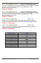
Pr 35 – External Keypad Input 1. [0 to 11, 0]
Allows an external normally open switch to be connected to the DRO and
emulate any key operation of the system. See: CIRCUIT BOARD JUMPER JP5 also.
Default = 0 (no key map)
Pr 36 – External Keypad Input 2. [0 to 11, 0]
Allows an external normally open switch to be connected to the DRO and
emulate any key operation of the system.
Default = 0 (no key map)
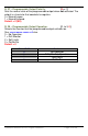
Value of Pr 35 & 36 Key
1
On/Off
2
Units
3
Plus
4
Datum
5
Minus
6
ABS/INC
7
Send
8
F1
9
F2
10
F3
11
F4