
Installation manual


Operation Manual for LCD Digital Readouts Page 36 of 48
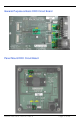
Circuit Board Jumpers
JP1 FACTORY USE ONLY
JP2 Encoder Technology Voltage Default = Position A
When this jumper is in the position A, the DRO is compatible with all current
ProScale 150, 250, 180, 280, 380 and 580 systems. In order to use this digital
readout with older ProScale Model 100 & 200 systems and other more recent
products based on Capacitive Incremental Technology, (see picture below) this
jumper must be set to the position B.
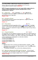
If your Scale looks like this: set JP2=B
There is NO JP2 Circuit Board Jumper on the Panel Mount DRO.
This readout does not support legacy Model 100 & 200 ProScale systems.
JP3 Programming Lock-out Default = Position A
Front panel programming of the Digital Readout can be enabled or disabled
though the use of this circuit board jumper.
Front panel Programming is enabled when the shorting jumper is installed in
position A. To disable Front panel Programming, install jumper on position B.
When programming is disabled, the user cannot access the programming
functions via the front panel as described in the Section 4: PROGRAMMING
PARAMETERS. This provides a method of configuring the Digital Readout with
specific parameters then preventing unauthorized or accidental configuration
changes.
JP4 DRO Power Selection Default = Position B
The General Purpose and Panel Mount DRO will operate on either on internal
battery power or external 24VDC. When this jumper is installed in position A,
the DRO is powered by an external DC power source via the power connector
When this jumper is installed in the B position, the DRO is powered from the
internal battery(ies).
JP5 Input/Output Selection Default = Position A
The General Purpose and the Panel Mount DRO have multipurpose connectors
used for External Power and, either an Input or Output connection. The Input &
Output functions are mutually exclusive. This jumper is used to configure the
connector to be used as an Input or an Output. In position A, the connector is
configured for OUTPUT. In the B position, the connecter is configured for
INPUT and is connected directly to the IN1 solder pad on the circuit board.
See: EXTERNAL KEYPAD INPUT & PROGRAMMABLE OUTPUT OPERATION UNDER ADVANCED
PROGRAMMING.