
Installation manual


Manual Part # 800-1402-001 Rev E Page 23 of 48
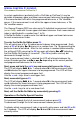
EXTERNAL KEYPAD INPUT
The multi-purpose connector on the General Purpose (GP) DRO and the circuit
board connections on the Panel Mount and GP DROs can be configured as
inputs providing the ability to simulate any front panel key press with an
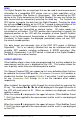
external switch. There are three solder pads on the DRO circuit boards, labeled
IN1, IN2 and GND (see below) that are used for key inputs. Any of the DRO’s
front panel keys may be mapped to respond to an external input. See
PROGRAMMING PARAMETERS Pr35 & Pr36 along with the associated Key Function
Mapping Table. The inputs must be from a normally open “dry” (no voltage
applied) switch, connected between ground (GND or common) and IN1 and/or
IN2. The switch input operates exactly the same as the mapped key providing
both momentary and “press and hold” functionality.
JUMPER JP5 on the DRO circuit board is set to allow the input/output terminal on
the GP 24 VDC power connector to be reconfigured as a direct connection to
IN1. (This allows for easy external interfacing without modifying the DRO
enclosure or soldering on the circuit board). Panel Mount DRO connections are
limited to the circuit board solder pads.
Pr35 maps a key to IN1. Pr36 maps a key to IN2.
CAUTION:. DO NOT APPLY VOLTAGE TO THESE INPUTS. These
inputs should only be switched to circuit negative.
Input
Circuit
Board
Solder
Pads
Jumper
JP5