
Installation manual


Operation Manual for LCD Digital Readouts Page 22 of 48
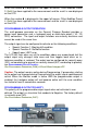
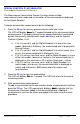
24VDC Input
Input
/
Output
Pin
Common
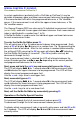
When the number 3
33
3 is displayed in the upper left corner, Offset Addition Preset
3 (PR33) has been applied to the measurement and the result is now displayed
on the LCD.
When the number 4
44
4 is displayed in the upper left corner, Offset Addition Preset
4 (PR34) has been applied to the measurement and the result is now displayed
on the LCD.
PROGRAMMABLE OUTPUT OPERATION
The multi-purpose connector on the General Purpose Readout provides a
power input connection and, a keyboard input or solid-state output (.1A / 30
VDC) connection. The input and output functions are mutually exclusive and
cannot be used at the same time.
The output signal can be configured to activate on the following conditions:
• Special Function 1: Monitor drift condition
• Special Function 2: Go/NoGo function
• Upper/Lower LIMIT error
The LCD will flash when any of the conditions above are encountered, but the
output signal only changes state once and then toggles back when an in-
tolerance condition is restored. The output can be configured for normally open
(N/O, not conducting to ground) or normally closed (N/C, conducting to ground),
see PROGRAMMABLE OUTPUT POLARITY.
See PROGRAMMING PARAMETER (Pr38) & Circuit Board Jumper JP5
Caution: The output remains active during Programming. If parameters relating
to the output are changed during Programming the output signal could become
active! When the Monitor mode is active AND the programmable output is
enabled, the hardware output will not become active until the error condition
has lasted at least 2 consecutive seconds.
PROGRAMMABLE OUTPUT POLARITY
The polarity of the programmable output signal when not activated is user
defined. The output is a transistor that conducts to Negative. The factory default
is normally open (NO).
See PROGRAMMING PARAMETER (Pr37).