
Installation manual


Manual Part # 800-1402-001 Rev E Page 21 of 48
SEND
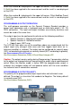
The Digital Readout has an output port that can be used to send measurement
information to a compatible SPC device such as a data acquisition unit or
wireless transmitter (See Section 6: Accessories). After connecting the SPC
device to the 10 pin connector on the Digital Readout, the user may initiate the
data transmission by momentarily pressing the SEND key. This instructs the
SPC device to acquire the data from the Digital Readout. Pressing the SEND
key will cause Snd
SndSnd
Snd to display on the LCD for 1 second to show activation of the
send function (even if no SPC device is attached to the Digital Readout).
All inch modes are transmitted as decimal inches. All metric modes are
transmitted as millimeters. The SPC position data transmitted is typically the
displayed position on the LCD with the exception of when Special Function
Mode is set to Measurement Accumulation or Statistics modes (See Special
Functions). In those modes, the displayed (calculated) values are sent, NOT
the current encoder position.
The data format and connector style of the DRO SPC output is Mitutoyo
Digimatic®. This is an industry standard that can be interfaced with most
available SPC products including multiplexers & RS232 converters (See
Section 6: Accessories). If no SPC device is attached to the Digital Readout,
the SEND key has no other function.
OFFSET ADDITION
Offset addition allows values to be pre-programmed that are then added to the
measurement and the sum is displayed on the LCD. This function allows the
user to quickly switch from one reference point to another.
The General Purpose DRO can support up to 4 user definable offsets that can
be added to the current ABS position. PROGRAMMING PARAMETER PR30 enables or
disables this function. For example: If PR30 = 2, only offset 1 and 2 are available
for use. PARAMETERS PR31 through PR 34 are the individual offset adders
respectively.
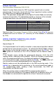
When enabled, the operator scrolls through the active offsets by pressing the
F1 key. The numbers 1,
1, 1,
1, 2, 3,
2, 3, 2, 3,
2, 3, 4
4 4
4 will be displayed in the upper left corner of
the LCD with each press of F1. When no numbers are displayed, no offset
addition is active.
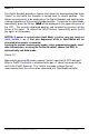
When the number 1
11
1 is displayed in the upper left corner, Offset Addition Preset
1 (PR31) has been applied to the measurement and the result is now displayed
on the LCD.
When the number 2
22
2 is displayed in the upper left corner, Offset Addition Preset
2 (PR32) has been applied to the measurement and the result is now displayed
on the LCD.