
Installation manual

Manual Part # 800-1402-001 Rev E Page 19 of 48
SEGMENT OFFSET ADJUSTMENT
This function applies to ProScale Model 150 & Model 250 systems and all other
ProScale products employing Absolute measurement technology that measure
more than 17 inches (430mm).
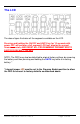
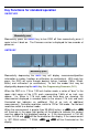
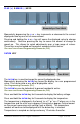
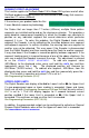
If the scale on your product looks like this:
It uses Absolute measuring technology
For Scales that are longer than 17 inches (430mm), multiple Scale pattern
segments are installed end-to-end on the aluminum extrusion. This provides a
quasi-absolute measurement capability in which the Encoder can calculate its
position on any individual segment but cannot determine which particular
segment it is on. To solve this problem, the Digital Readout tracks which
segment the Encoder is on by detecting the transition between one segment
and adjacent segments. In certain situations, the crossing from one segment to
another may not be detected. This may occur if the Encoder is disconnected
from the Digital Readout and then moved along the Scale to another segment.
It may also occur if the Encoder is moved too quickly between segments. If the
segment tracking count is incorrect because of one of the above situations, the
user can re-adjust the Readout to correct the error. This adjustment is referred
to as the SEGMENT OFFSET ADJUSTMENT. To add one segment value
(430.08mm) to the displayed value, press and hold the UNITS key and then
momentarily press the + key. The displayed position will increase by
430.08mm (16.933 inches). To subtract one segment, 430.08mm, from the
displayed value, press and hold the UNITS key and then momentarily press the -
key. This function is operative only when Pr14 is set to 1.
See Programming Parameter (Pr14).
UPPER/LOWER LIMITS
The Digital Readout can display either LL
LLLL
LL for Lower Limit or UL
ULUL
UL for Upper Limit
if a pre-programmed upper or lower reading is exceeded. Upper and Lower
Limits are set with Programming Parameters Pr28 and Pr29 but are only active if
Pr27 is set to 1. The LCD display toggles for 2 seconds between current
position and LL
LLLL
LL if the Lower Limit is exceeded, or UL
ULUL
UL if the Upper Limit is
exceeded. This continues as long as either limit is exceeded.
See Programming Parameters (Pr27, 28, 29).
In addition, the programmable output can be configured to activate on General
Purpose Digital Readouts when either the Upper or Lower limit is exceeded.
See PROGRAMMABLE OUTPUT OPERATION.