
Installation manual

Manual Part # 800-1402-001 Rev E Page 11 of 48
SECTION 2 SET-UP
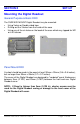
Mounting the Digital Readout
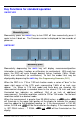
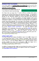
General Purpose & Basic DRO
The SURFACE MOUNT Digital Readout may be mounted:
• Using Velcro or Double sided tape
• Drilling out the 3 holes from the inside of the case
• Using any of the six holes on the back of the case which may tapped for M2
or 4-40 screws.
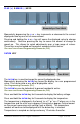
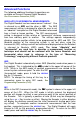
Panel Mount DRO
A cutout should be made in the panel at least 90mm x 90mm (3.6 x 3.6 inches),
but no larger than 93mm x 93mm (3.7 x 3.7 inches).
The cases of the Digital Readout are designed to "sandwich" panel thicknesses
between 3mm (0.125") and 20mm (0.750") between the front and rear Digital
Readout cover.
NOTE: If Panel is thinner than 3mm (0.125 in), shorter screws must be
used for the Digital Readout casing or damage to the front cover of the
Digital Readout will occur.