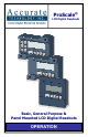
ProScale® LCD Digital Readouts Basic, General Purpose & Panel Mounted LCD Digital Readouts OPERATION
WARRANTY Accurate Technology, Inc., warrants the ProScale® Digital Measuring Systems against defective parts and workmanship for 1 year commencing from the date of original purchase. Upon notification of a defect, Accurate Technology, Inc., shall have the option to repair or replace any defective part. Such services shall be the customer's sole and exclusive remedy.
Table of Contents SECTION 1 GENERAL INFORMATION .................................................................... 6 INTRODUCTION.........................................................................................................................6 ABOUT THIS MANUAL .................................................................................................................7 DIGITAL READOUT SPECIFICATIONS ............................................................................................
CHANGING THE BATTERY...........................................................................................................35 CIRCUIT BOARD JUMPERS .........................................................................................................36 General Purpose & Basic DRO Circuit Board.......................................................................37 Panel Mount DRO Circuit Board ........................................................................................
FCC NOTICE This equipment has been tested and found to comply with the limits for a class B digital device, pursuant to part 15 of the FCC Rules. These limits are designed to provide reasonable protection against harmful interference in a residential installation. This equipment generates, uses and can radiate radio frequency energy and if not installed and used in accordance with the instructions, may cause harmful interference to radio communications.
SECTION 1 GENERAL INFORMATION Introduction ProScale® digital measuring systems are affordable precision electronic devices for making linear measurements with speed and accuracy. ProScale consists of a SCALE, an ENCODER (also called READHEAD) and a DIGITAL READOUT (DRO). ProScale Models 150 and 250 use Capacitive Absolute measuring technology, while the Model 180, 280, 380 & 580 systems use Inductive Incremental measuring technology. ProScale is ideal for most measuring requirements up to 6m (20ft.
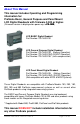
About This Manual This manual includes Operating and Programming information for: ProScale Basic, General Purpose and Panel Mount LCD Digital Readouts with firmware 3.000 or higher. (Firmware version is displayed on power-up, ie P3.000) P3.
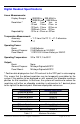
Digital Readout Specifications Linear Measurements: Display Ranges: Resolution:* Repeatability: + 999.999 in; + 399 63/64 in + 9999.99 mm; + 999.999 cm .1inch .1mm .1cm or .01inch .01mm .01cm or .001inch .01mm .001cm or .0005inch .01mm .001cm .001in or .01mm or .001cm Temperature Measurement: Accuracy: + 1º C from 0 to 70º C, + 2º C otherwise. Resolution: .
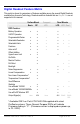
Digital Readout Feature Matrix This matrix is shown for comparison of features available among the several Digital Readouts available from Accurate Technology. Readouts and their features that are Grayed Out are not supported in this manual.
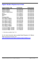
Digital Readout Replacement Chart Digital Readout Type General Purpose General Purpose General Purpose General Purpose Basic Basic Standard SPC Programmable Panel Mount, Battery Panel Mount, Battery Panel Mount, 24VDC Panel Mount, Battery Panel Mount, Battery Panel Mount, 24VDC Panel Mount, Battery Panel Mount, 24VDC Incremental Model 100/200 Incremental Model 100/200 Incremental Model 100/200 Old Number 700-1600-225 700-1600-200 700-1600-001 700-1600-220 701-1495-001 701-1500-00x 701-1505-00x 701-1115-00x
SECTION 2 SET-UP Mounting the Digital Readout General Purpose & Basic DRO The SURFACE MOUNT Digital Readout may be mounted: • Using Velcro or Double sided tape • Drilling out the 3 holes from the inside of the case • Using any of the six holes on the back of the case which may tapped for M2 or 4-40 screws. Panel Mount DRO A cutout should be made in the panel at least 90mm x 90mm (3.6 x 3.6 inches), but no larger than 93mm x 93mm (3.7 x 3.7 inches).
24VDC Operation The General Purpose and the Panel Mounted LCD Digital Readouts will operate on batteries or 24VDC. The General Purpose Readout uses a multipurpose plug-in connector for power as well as input and output signals. The Panel Mount Readout uses screw terminals for these connections. (Connections can be configured as outputs or inputs, but not both at the same time).
The LCD The above figure illustrates all the segments available on the LCD Pressing and holding the ON/OFF and UNITS key for 10 seconds with power OFF will perform a full segment LCD test, display the current firmware version, AND RESET ALL PROGRAMMING PARAMETERS TO FACTORY DEFAULT VALUES. NOTE: The DRO may also be defaulted to original factory settings by removing the battery and then pressing and holding the UNITS key while re-inserting battery.
SECTION 3 OPERATION Fundamental Operation The following operations & functions apply to the Basic, General Purpose and Panel mount LCD Digital Readouts. KEY TIMING The keys pictured below have multiple functions. Timing (how long a key is depressed) is important. This manual uses the term “momentarily” to describe a key press and release of less than .8 seconds. Whereas “press and hold” is used to describe a key press and release of 1 second or longer.
Key Functions for standard operation ON/OFF KEY Momentarily press Momentarily press the ON/ OFF key to turn DRO off then momentarily press it again to turn it back on. The Firmware version is displayed for two seconds at power-on. UNITS KEY Momentarily press Momentarily depressing the UNITS key will display measurement/position information in inches, fractions or millimeters (or centimeters).
PLUS (+) & MINUS (–) KEYS Momentarily or Press & Hold Momentarily depressing the + or – key increments or decrements the current displayed value by one unit of measurement. Pressing and holding the + or – key will cause the displayed value to change continuously. Continue pressing the key to cause the amount of change to speed up. This allows for quick adjustments over a large range of values. These keys may be locked out to prevent accidental offset entries.
Basic Functions MEASUREMENT READING DIRECTION Once the system has been put into operation, if the direction of readings, (positive or negative values) is opposite the desired direction, the DRO programming may be changed to correct the direction. See Programming Parameter (Pr2). KEY LOCK The Digital Readout provides a function that can be used to “lock-out” the position offset adjustment keys (+, DATUM , –) to prevent accidental changes of the current displayed value.
DISPLAYED MEASUREMENT UNITS The measurement units displayed on the Readout when the UNITS key is depressed is user configurable. The table below provides a matrix for selecting which units will be displayed (based on the value entered in programming parameter Pr11). See Programming Parameter (Pr11).
SEGMENT OFFSET ADJUSTMENT This function applies to ProScale Model 150 & Model 250 systems and all other ProScale products employing Absolute measurement technology that measure more than 17 inches (430mm). If the scale on your product looks like this: It uses Absolute measuring technology For Scales that are longer than 17 inches (430mm), multiple Scale pattern segments are installed end-to-end on the aluminum extrusion.
Advanced Functions The following additional functions & operations are available on General Purpose Digital Readouts See PROGRAMMING PARAMETER (Pr23). ABSOLUTE VS INCREMENTAL MEASUREMENTS. The Digital Readout has two measurement “indexes”. One is referred to as ABS and the other is INC. The ABS measurement setting is designed to allow the user to set an “absolute“ zero point on the Digital Readout referenced from a fixed or known position.
SEND The Digital Readout has an output port that can be used to send measurement information to a compatible SPC device such as a data acquisition unit or wireless transmitter (See Section 6: Accessories). After connecting the SPC device to the 10 pin connector on the Digital Readout, the user may initiate the data transmission by momentarily pressing the SEND key. This instructs the SPC device to acquire the data from the Digital Readout.
When the number 3 is displayed in the upper left corner, Offset Addition Preset 3 (PR33) has been applied to the measurement and the result is now displayed on the LCD. When the number 4 is displayed in the upper left corner, Offset Addition Preset 4 (PR34) has been applied to the measurement and the result is now displayed on the LCD. PROGRAMMABLE OUTPUT OPERATION The multi-purpose connector on the General Purpose Readout provides a power input connection and, a keyboard input or solid-state output (.
EXTERNAL KEYPAD INPUT The multi-purpose connector on the General Purpose (GP) DRO and the circuit board connections on the Panel Mount and GP DROs can be configured as inputs providing the ability to simulate any front panel key press with an external switch. There are three solder pads on the DRO circuit boards, labeled IN1, IN2 and GND (see below) that are used for key inputs. Any of the DRO’s front panel keys may be mapped to respond to an external input.
SPECIAL FUNCTIONS See PROGRAMMING PARAMETERS (Pr24, 25, 26) Special Function Mode allows the DRO to perform special tasks or custom programming. These tasks interact with the F keys to perform functions related to a specific task or programming operation. Note: The operations configurable via the Special Function Mode are mutually exclusive of each other. The table below provides a summary of the included standard operations and each feature is further defined below.
Hold: F4 The Digital Readout provides a feature that allows the displayed position to be “frozen” in time while the Encoder is moved from its current position. This allows measurements to be captured on the Digital Readout and held for later viewing regardless of the current Encoder position. To activate the Hold Mode, momentarily press the F4 key. HOLD will be displayed in the upper left corner of the LCD. The currently displayed position and selected key presses will be frozen at this point.
SPECIAL FUNCTION 2: GO/NOGO PROGRAMMING PARAMETER Pr24 set to 2 In certain applications (particularly with a ProTable or ProPanel) it may be desirable to program upper and lower measurement tolerances to gauge parts. If the measurement falls within the programmed tolerance, a “Go” condition occurs. If the measurement is not within the upper or lower tolerance, a “No Go” condition occurs.
SPECIAL FUNCTION 3: ACCUMULATOR PROGRAMMING PARAMETER Pr24 set to 3 The Measurement Accumulator Special Function allows multiple measurements to be made and a summation of the measurements displayed on the Digital Readout. To begin accumulation measurements do the following: 1. Press the F4 key to view any previous accumulator total value. The LCD will display Accu for 1 second followed by the total accumulated measurements.
4. View Accumulated Total. To view the accumulated total, press the F4 key. The following options are now available: a. Press F3 to clear the total and return to the measuring mode. b. Press F4 (DOES NOT clear the accumulation total) to return to the measuring mode. c. Press SEND to transmit the accumulated total to the SPC port. NOTE: Measurement Accumulation mode maintains a running summation of the measurements taken. Individual measurements in the summation series cannot be edited or deleted.
SPECIAL FUNCTION 4: STATISTICS PROGRAMMING PARAMETER Pr24 set to 4 The General Purpose Digital Readout can perform some basic statistical analysis without the use of SPC data collection on a PC or other device. The DRO’s Statistics mode can provide the following functionality: 1. Measurement Count. 2. Minimum Measurement. 3. Maximum Measurement. 4. Average Measurement in two modes: a. Standard average (Measurement Sum ÷ Count) b.
c. Press the SEND key to transmit the Maximum Measurement to the SPC port. Press the F4 key again and the LCD will display either AG or AAG depending on the setting of the Special Function Option parameter, PR 25. If PR 25 is set to 0, the Standard Averaging method is used and the LCD displays AG for 1 second followed by the Standard Average: (Measurement Sum ÷ Count) If PR 25 is NOT set to 0, the LCD displays AAG for 1 second followed by Trimmed Average ((Measurement Sum - Max - Min) ÷ (Count - 2)) a.
Compensation Functions NOTE: The following features are available ONLY on General Purpose Digital Readouts with firmware ending in ‘C”, (Part # 700-1600-236) supplied on ProScale Model 580 and ProTable systems. (The firmware version is displayed on power-up, ie P3.000C). TEMPERATURE COMPENSATION This feature provides automatic compensation of measurement variations caused by changes in the ambient temperature where the measurement system is being used.
NON-LINEAR COMPENSATION This function is used to enhance the basic accuracy of the ProScale system by creating a table of correction values in the DRO based on known measurement points along the length of the measurement system. The compensation table consists of 126 elements. This should provide adequate compensation for any length measurement system currently manufactured by Accurate Technology.
3. Turn the Digital Readout off. Press and hold down the DATUM key and the ON/OFF key for approximately 10 seconds. After that time, the LCD will turn on and complete a segment test. You can release the ON/OFF and DATUM keys at this time. 4. After the LCD test is complete, the Readout will show the firmware version for about 1 second. This will be followed by the LCD showing the current position alternating with cal . This indicates the Digital Readout is in the correction table calibration mode.
Operating the system in compensated mode. After a successful correction table has been programmed, the DRO will operate normally and the measuring system will have a higher level of accuracy. If the encoder is positioned outside the calibrated range of operation, the LCD will display No Co alternately with the current position. This indicates that the system is operating outside the calibrated measuring range and has a reduced measuring accuracy.
Changing the Battery A low battery indicator will appear in the lower left corner of the LCD. Press and hold DATUM key for 6 seconds to display the Battery Voltage. When battery voltage drops below approximately 2.6V the DRO will turn itself off until the batteries are replaced. To replace the battery: General Purpose & Basic Digital Readouts: Remove the screws in the upper right and lower left corners. Pull the cover off. Remove the old batteries.
Circuit Board Jumpers JP1 FACTORY USE ONLY JP2 Encoder Technology Voltage Default = Position A When this jumper is in the position A, the DRO is compatible with all current ProScale 150, 250, 180, 280, 380 and 580 systems. In order to use this digital readout with older ProScale Model 100 & 200 systems and other more recent products based on Capacitive Incremental Technology, (see picture below) this jumper must be set to the position B.
General Purpose & Basic DRO Circuit Board JP3 JP4 JP2 JP5 Panel Mount DRO Circuit Board JP3 JP4 JP5 Manual Part # 800-1402-001 Rev E Page 37 of 48
SECTION 4 PROGRAMMING Several functions of the Digital Readouts are user programmable. The following describes what features and functions are available and how to change the factory defaults to customize your Digital Readout. To enter Programming Mode: 1. Press and hold the UNITS key then momentarily press the DATUM key. 2. The LCD will briefly display: PG on (Programming On), then Pr 1, 1 (indicating Programming Parameter #1) 3. Release the UNITS key 4. The value stored for Pr1 is displayed.
The Digital Readout Programming Parameters are listed below. Values in [ ] are the range of values available for that Parameter. Factory defaults values are shown in Bold Red. NOTE: Programming parameters are not sequentially numbered due to firmware differences between systems and provision for future enhancements / features. Pr 1 – Datum Key [0 to + 999.999in] or [0 to +9999.99mm] The programmed value that will be recalled whenever the Datum key is pressed during normal operation. Default = 0.
Pr 11 – Displayed Measurement Units [0 to 6, 0] This parameter controls the type of measuring units that will be displayed on the DRO. The table below illustrates the possible combinations of measuring units that can be configured by changing the value of this programming parameter.
Pr 21 – Backlight Control [0 to 10] (Panel Mount DROs only.) If the Backlight Option is ordered, this parameter controls the amount of time, in seconds the backlight is on when either a key press or motion is detected. 0 = Always Off, 10 = Always On, 1 – 9 is in seconds of ON time. Default = 10 (Always On) Pr 22 – ABS/INC Key Operation [0 or 1] (General Purpose DROs only.) This controls the amount of time the ABS/INC key needs to be pressed to enter the INCremental measuring mode.
Pr 26 – Position Monitor Drift Tolerance. [.0004” to 120”, .01”] This parameter sets the amount of drift that must occur in MONitor mode to trigger a drift condition indication. Default = .01” Pr 27 – Use Soft Limits. [0 or 1] Enables or disables the use of soft limits. If enabled, a message on the LCD is displayed when the measuring system is operating outside the programmed (Pr 28 & Pr 29) position limits. 0 = off, 1 = on. Default = 0 (off) Pr 28 – Lower Soft Limit Position.
Pr 33 – Offset Addition Preset 3. Range: Any displayable position This value is added to the current ABS position when Offset Addition is enabled (Pr 30 not set to 0) and Offset Preset 3 is selected with the F1 key. (3 segment displayed on LCD). Default = 3” (76.2mm) Pr 34 – Offset Addition Preset 4. Range: Any displayable position This value is added to the current ABS position when Offset Addition is enabled (Pr 30 not set to 0) and Offset Preset 4 is selected with the F1 key.
Pr 37 – Programmable Output Polarity. [0 or 1] Sets the normal state of the programmable output when not activated. The output is a transistor that conducts to negative. 0 = Normally open. 1 = Normally closed. Default = 0 (NO) Pr 38 – Programmable Output Operation. [0, to 3, 0] Selects the function that the programmable output activates on. See: CIRCUIT BOARD JUMPER JP5 also. 0 – No Operation.
The following Programming Parameters are available only on General Purpose DROs with firmware ending in “C” (part # 700-1600-236). Pr 39 – Non-Linear Compensation Enable. [0 or 1] Enables or disables the Non-Linear Compensation feature of the DRO. Default = 0 (off) Pr 40 – Non-Linear Compensation Interval. [0.5 to 10.0, 5.0] Sets the distance interval used while performing non-linear compensation calibration. Default = 5” (127mm) Pr 41 – Temperature Compensation Enable.
SECTION 5 MISCELLANEOUS Frequently Asked Questions What does no Enc mean? If the Encoder is off the Scale, or the Encoder cable is unplugged from the Digital Readout, no Enc will appear on the LCD. To clear: 1. Be sure the Encoder is on the Scale and properly oriented. 2. Unplug the Encoder from the Digital Readout for one second and then reconnect the Encoder. 3. Connect the Encoder to the Digital Readout.
SECTION 6 ACCESSORIES ProRF SPC ProRF allows linear measurement or position data to be transmitted wirelessly to a PC or other device having a USB or RS232 connection. The system uses 802.15.4 radio modules to provide reliable two way communication. The transmitter plugs into any Digital Readout with an SPC output.
Thank you for choosing a ProScale Product, IT WAS PROUDLY MADE IN THE USA Accurate Technology, Inc. 270 Rutledge Rd. Unit E Fletcher, NC 28732 USA 828-654-7920 www.proscale.com Please register your system at: www.proscale.com/registration.htm P/N 800-1402-001 Rev E Copyright © 2010, Accurate Technology, Inc. All rights reserved.