ProScale™ Model 150 Model 250 User’s Manual for: ProScale Model 150 & 250 Systems & All ProScale Products using the General Purpose LCD Digital Display Firmware V2.
Warranty Accurate Technology, Inc., warrants the Model 150 and Model 250 ProScale against defective parts and workmanship for 3 years commencing from the date of original purchase. Upon notification of a defect, Accurate Technology, Inc., shall have the option to repair or replace any defective part. Such services shall be the customer's sole and exclusive remedy.
Table of Contents SECTION 1 GENERAL INFORMATION ............................................................................... 5 Introduction....................................................................................................................................... 5 What This Manual Includes ............................................................................................................... 5 ProScale Terminology......................................................................
Fully Programmable, 24VDC ........................................................................................................ 23 Mounting the Panel Mount Display ............................................................................................... 23 Display Operation ........................................................................................................................... 24 The LCD .............................................................................................
SECTION 1 GENERAL INFORMATION Introduction ProScale™ digital measuring systems are affordable precision electronic devices for making linear measurements with speed and accuracy. ProScale consists of a scale, a readhead (or encoder) and a digital display. It uses capacitive encoder technology, the same technology used in digital calipers. Because ProScale is a solid-state electronic device there's very little to wear out.
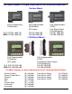
The General Purpose LCD Digital Display comes in the following configurations: Surface Mount Basic Programming 2AA Batteries OLD P/N 701-1600-120 NEW P/N 700-1600-220 Fully Programmable 2AA Batteries SPC output P/N 701-1600-100 P/N 700-1600-200 Fully Programmable 24VDC Limit Signal Output LCD Backlighting P/N 701-1605-100 P/N 700-1600-205 ¼ DIN Panel Mount Fully Programmable 2D Batteries SPC output Fully Programmable 24VDC Limit/Monitor Signal Output LCD Backlighting P/N 701-1560-100 P/N 700-1600-300
ProScale Terminology All ProScale systems consist of a SCALE, a READHEAD, and a DIGITAL DISPLAY. The SCALE consists of a series of conductive patterns bonded to an aluminum extrusion. The READHEAD, or encoder, contains a computer chip which transmits and receives signals to and from the scale using capacitive coupling. The received signal is used by the readhead to calculate its position to within 10 microns (10µm / .0004in).
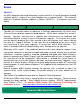
Scales Absolute An (ABS) Absolute measuring technology system measures its actual position by reading a pattern which is unique at any given location over a segment length. The maximum length of a ProScale absolute segment is 430mm (16.932 in.). The segment must then repeat. Consider the illustration above to represent a ProScale approximately 50 inches long. There are three absolute segments joined together. Within each segment the system is absolute.
Incremental Simply stated, an Incremental system measures the distance it has traveled relative to a starting point. Incremental style scales have a repeating “bar” pattern on a green laminate. There should be a “SPLICE” approximately every 570mm (22in.). Incremental scales may be shortened if needed. Incremental Style Pattern Scales used on Absolute and Incremental systems should never be mixed. Avoid drilling through the green portion of any scale.
Readheads Absolute Absolute (ABS) style readheads have “BLACK END OF SCALE” labels on the cover, and the wire exits from the corner of the housing. Care must be taken not to damage the brass “fingers” inside the readhead housing. ABS style readheads, used in all Model 150 and Model 250 systems, must only be used on ABS scales and with a particular orientation. Each readhead has an arrow on the label pointing in the direction of the “BLACK END OF SCALE”. Each ABS style scale will have one end painted black.
Digital Displays Accurate Technology makes several different digital displays for use with ProScale products. Each display has unique features that make it suitable for different applications. The following is a listing of the displays and their descriptions: General Purpose Surface Mount Basic (no auxiliary keys) 2AA Bat.
Product Specifications ProScale Model 150 & Model 250 Measuring Range*: Model 150: 2 Standard Sizes: 0-250mm (10in) and 0-450mm (18in) Model 250: 9 Standard Sizes: 0 to 300mm, 600mm, 1.3m, 2.4m, 3.0m, 3.6m, 6.0m (0 to 12in, 24in, 52in, 96in, 120in, 144in, 240in ) Accuracy: + (.025 + .064 x L / 430) mm; max error + 0.20mm @ 1.3 to 6m + (.001 + .0025 x L / 17) in; max error + .008in @ 4 to 20 feet (L = length of measurement in mm or inches) Resolution .1mm/.01cm/.01in; .01mm/.001cm/.001in; .01mm/.001cm/.
SECTION 2 PROSCALE MODEL 150 ProScale Model 150-10 shown with Surface Mount General Purpose LCD Digital Display ProScale Model 150 A General Purpose measuring system with standard measuring ranges of 250mm (10”) or 450mm (18”). Model 150 systems use ABS style scales, ABS style readheads, and any of the available digital displays. Neither the scale nor readhead are compatible with any Accurate Technology incremental technology measuring systems. ProScale Model 150 is easy to install.
Installation 1. Note the orientation of the readhead on the scale. Be sure the arrow on the readhead points towards the “BLACK END OF SCALE”. This orientation is critical for proper operation of ProScale. Be sure the mounting location for the readhead and scale will allow this orientation. Take care when sliding the readhead onto the scale so the brass “fingers” inside the readhead do not get damaged. (A slight “wiggling” motion when installing the readhead on the scale will simplify the process.) 2.
5. The Digital Display may be mounted in a location which allows for easy viewing by the operator. The location of all parts should also safeguard the cable from possible damage. ProScale wiring should be kept away from electrical wiring and motors. Plug the readhead into the display. See Section 4: Digital Display Operation.
Calibration Once installed, ProScale can be calibrated easily and quickly. Following is an example for calibrating ProScale on an industrial wide belt sander. Other installations follow the same general procedure. 1. Check to be sure installation of all parts is complete, all fasteners are secure, and the readhead is plugged into the digital display. 2. Set-up the machine to operate as normal. Run a part through the sander. 3.
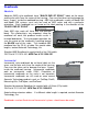
SECTION 3 PROSCALE MODEL 250 ProScale Model 250 shown with Panel Mount General Purpose LCD Display ProScale Model 250 A General Purpose measuring system with nine standard measuring ranges from 0-300mm (12in.) up to 0-6m (20ft.). Model 250 systems use ABS style scales, ABS style readheads, and any of the available digital displays. Neither the scale nor readhead are compatible with any Accurate Technology incremental technology measuring systems. ProScale Model 250 is easy to install.
Installation 1. Note the orientation of the readhead on the scale. Be sure the arrow on the readhead points towards the “BLACK END OF SCALE”. This orientation is critical for proper operation of ProScale. Be sure the mounting location for the readhead and scale will allow this orientation. Take care when sliding the readhead onto the scale so the brass “fingers” inside the readhead do not get damaged. (A slight “wiggling” motion when installing the readhead on the scale will simplify the process.) 2.
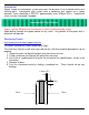
Typical Model 250 Installation M o vin g P a rt G u id e C lip M o d e l 2 5 0 S ca le R eadhea d G u id e C lip R e a d he a d 2 1 .2 m m (.8 3 " ) M o d e l 2 5 0 S c a le 3 3 .0 m m ( 1 .
Calibration Once installed, ProScale can be calibrated easily and quickly. Following is an example for calibrating ProScale on a table saw fence. Other installations follow the same general procedure. 1. Check to be sure installation of all parts is complete, all fasteners are secure, and the readhead is plugged into the digital display. 2. Cut a part using the normal fence operation. 3. Do Not move fence until calibration is completed. 4.
SECTION 4 DIGITAL DISPLAY OPERATION This section covers the installation, programming and operation of the General Purpose LCD Digital Display (Firmware V2.0 and higher). This display is supplied on ProScale Model 150 and Model 250 systems (covered in this manual) as well as several other ProScale products whose operation is covered in their respective manuals but the digital display information is contained here.
Fully Programmable, Battery Operation This display operates on 2AA batteries. It includes all the features of the BASIC display plus: It has an auxiliary keypad with 6 keys for: switching between ABSolute readings and INCremental measurements, MONitoring position drift, SENDing data out the SPC connector, HOLDing the reading, and F1 & F2 special function keys. This display does not have Limit Alarm / Monitor Output, or Back-Lighting.
Panel Mount Displays The General Purpose LCD Display for panel and enclosure mounting applications comes in two versions. Both are designed to fit a ¼ DIN (90mm x 90mm) (3.5in x 3.5in) panel opening. One version is battery operated (2D) and the other is designed for 24VDC operation. Both versions have full programming capability.
Display Operation The LCD The above figure illustrates all the segments available on the Digital Display. CAUTION: Pressing and holding the ON/OFF and MODE key for 10 seconds while the display is turned off will perform a full segment LCD test AND re-set all programming parameters to factory defaults Display Keys Timing The keys pictured above, found on all General Purpose LCD Digital Displays, have multiple functions.
ON/OFF Momentarily pressing the ON/OFF key will cause the display to turn on or off. The Firmware Version is displayed on power-up or when ON/OFF key is pressed. While on, if no key presses or positional changes occur within 15 minutes, the Digital Display will automatically turn itself off to conserve battery life. While off, if a position change is detected (.05mm or .002in) or the ON/OFF button is pressed, the display will automatically turn itself on with no loss of measurement information.
+, 0, and – Keys The + (plus), 0 (zero) and – (minus) keys are used to change the currently displayed position to a different value. The 0 key forces the unit to display 0. Momentarily depressing the + key increments the current position by one unit of measurement. Momentarily depressing the – key decrements the current position by one unit. Pressing and holding the + or – keys will cause the displayed position to change continuously. Holding down the key will cause the amount of change to speed up.
Offset Addition Offset addition allows the user to preset up to 3 different distances that are then added to the Digital Displays position when selected. This allows the user to quickly switch measurement modes from one reference point to another such as in the case of inside and outside measurements on ProPanel or multiple stations on a vertical panel saw. To utilize the offset addition feature, programming parameter Pr10 must be set to 1.
24VDC Operation The 24VDC Digital Displays have some additional functions that are not available on battery powered displays. The 24VDC displays are designed to run on DC voltage ONLY. DO NOT ATTEMPT TO OPERATE THESE DISPLAYS USING AC VOLTAGE COMMON SPC output SIGNAL SPC output Readhead Input 12-24VDC Surface Mount Above, Panel Mount Right 12-24VDC COMMON SIGNAL OUTPUT Readhead Input Limit/Monitor Signal Output This function is available on 24VDC powered Digital Displays ONLY.
Auxiliary Keypad As seen on the Panel Mount Display As seen on the Surface Mount Display The Auxiliary Keypad is found only on Digital Displays that are Fully Programmable (See Programming Parameter 9. Factory default is all keys enabled.) ABS - INC The Digital Display has two measurement “indexes”. One is referred to as ABS and the other is INC.
MONitor The Digital Display has the ability to monitor a position to detect position drift or measurement variance. To activate the monitoring mode, position the readhead to the desired location and momentarily press the MON key. The MON symbol will flash on the display to indicate that the position monitor mode is active. If the readhead moves outside the programmed tolerance the displayed reading flashes, indicating a drift condition.
Programming Several functions of the digital display are user programmable. The following instructions describe what features are available and how to change the system’s factory defaults to customize the display for your application. The keys pictured have multiple functions. Timing, which is how long a key is depressed, and the combination of the keys pressed is important. This manual uses the term ‘”momentarily” to describe a key press of typically less than 1 second.
Programming Parameters are listed below. Values in [ ] are the available range of values that can be programmed for that entry. Factory defaults are shown in bold. Pr0 – Encoder Direction [0,1] Change value to reverse the direction of measurement readings. Pr1 – Enable/Disable Segment Offset [0, 1] 0 = For ABSOLUTE scales shorter than 430mm, (16.9in). ALL Incremental scales 1 = For All ABSOLUTE scales longer than 430mm, (16.9in).
Pr8 – Automatic Power Off [0 to 60] Default = 15. Sets the amount of time in ‘minutes without activity’ before the display automatically turns off. 0 = Disables Auto Off. Encoder motion or ON/OFF key “wake-ups” the display and resets the timer. Pr9 – Auxiliary Keys Enable/Disable [0..7] 0 = ABS/INC, MON and HOLD Disabled 1 = ABS/INC Key Enabled 2 = MON Key Enabled 4 = HOLD Key Enabled 7 = All Keys Enabled To enable keys, add up combination of key values. A value of 2 enables only the MON key.
Pr15 – Output Polarity [0, 1]. Used to configure the signal output. N/O or N/C in relation to circuit ground. 0 = N/O, the output is Normally Open (not conducting to ground). 1 = N/C, the output is Normally Closed (conducting to ground). Pr16 – Lower Limit [-999.999 to 999.999in] or [-9999.99 to 9999.99mm] Sets the lower limit alarm value. Default = 0.000IN. Active only when parameter Pr14 = 1. Note: Default is set in Inches Pr17 – Upper Limit [-999.999 to 999.999in] or [-9999.99 to 9999.
Jumpers – Surface Mount Display Although the ProScale display uses a keyboard-programming mode to enable and configure features in the unit, several selection jumpers are located on the circuit board for additional system configuration. User configurable jumpers consist of three pins and a ‘shorting block’. The center of these pins is ‘Common’. One end pin is labeled ‘A’ and the other end pin is labeled ‘B’.
Jumpers – Panel Mount Display Although the ProScale display uses a keyboard-programming mode to enable and configure features in the unit, several selection jumpers are located on the circuit board for additional system configuration. User configurable jumpers consist of three pins and a ‘shorting block’. The center of these pins is ‘Common’. One end pin is labeled ‘A’ and the other end pin is labeled ‘B’.
Programming Summary Programming Parameter Pr0 Pr1 Pr2 Pr3 Pr4 Pr5 Pr6 Pr7 Pr8 Pr9 Pr10 Pr11 Pr12 Pr13 Pr14 Pr15 Pr16 Pr17 Pr18 Pr19 Pr20 Pr21 Pr22 Pr23 Pr24 Pr25 Function Encoder Direction Segment Offset High Speed ReadHead Zero, Offset Entry Display Resolution mm or cm Fractions, mm, in Scaling Auto off Auxiliary Keypad Offset Addition Offset Addition 1 Offset Addition 2 Offset Addition 3 Output Mode Output Polarity Lower Limit Upper Limit Drift Tolerance Auto Monitor ON Auto Monitor OFF Auto Monitor Dis
Jumpers and Key Press Summary Circuit Board Jumpers JUMPER SURFACE MOUNT DISPLAY JP1 Internal Use Only JP2 Absolute (ABS) or Incremental System JP3 Programming Enable/Disable JP4 Display Power – Battery or 24VDC JP5 Internal Use Only PANEL MOUNT DISPLAY Power Selection (set same as JP2) Power Selection (set same as JP1) Programming Enable/Disable Internal Use Only N/A Key Press Functions: ON/OFF (Press & Hold) + MODE (Momentarily) Enable/Disable LOCK mode (‘0’, ‘+’ & ‘-‘ keys).
SECTION 5 MISCELLANEOUS Frequently Asked Questions What does “no Enc” mean? If the readhead is off the scale, or the readhead cable is unplugged from the digital display, an “no Enc” will appear on the display. To clear error: 1. Be sure the readhead is on the scale. 2. Unplug the connector from the display for one second. 3. Reconnect the readhead cable to the digital display. The battery clips seem to be very loose. Is this normal? Yes.
Abbe Error Abbe error is a condition that may not be visible to the human eye, but will affect linear measurements. Be sure to take precautions when installing ProScale in order to eliminate the possibility for Abbe error. Abbe error refers to a linear error caused by the combination of an angular error and a dimensional offset between the sample and the measuring system. It is important to understand that the information the encoder is providing is only the position of the readhead on the scale.
SECTION 6 ProMUX-3™ ACCESSORIES ProMUX-8™ ProRF™ AIU™ The ProMUX 3 is an easy to use hardware interface device providing communication and control of one to three ProScale ABS linear encoders from a user provided PC or PLC. ProMUX-3: 1, 2 or 3 INPUTS; 1 RS232 OUTPUT The ProMux-8 multiplexer is designed for OEM and system integrators for use in acquiring setup positional information (non-CNC) on industrial production machinery.
SECTION 7 Description Part Number Digital Display, LCD, (Fully Programmable) 700-1600-200 Digital Display, LCD, (Fully Programmable) 700-1600-205 Digital Display, LCD, (Basic) 700-1600-220 Digital Display, LCD, 1/4 DIN Panel Mount 700-1600-300 Digital Display, LCD, 1/4 DIN Panel Mount 700-1600-400 Readhead, ABS, 12 inch cable 701-1500-012 Readhead, ABS, 24 inch cable 701-1500-024 Readhead, ABS, 36 inch cable 701-1500-036 Readhead, ABS, 72 inch cable 701-1500-072 Readhead, ABS, 120 inch cable 701-1500-120 Re
PRODUCT REGISTRATION Fill out for your records and FAX to Accurate Technology @ +1.828.654.8824 or Register on line at http://www.proscale.com/registration.
Thank you for choosing a ProScale Product MADE IN USA Accurate Technology, Inc. 270 Rutledge Rd. Unit E Fletcher, NC 28732 USA 800 233-0580 • 828-654-7920 Fax 828-654-8824 www.proscale.com customerservice@accurate-technology.com This manual is available at www.proscale.com Please return your Product Registration Card or register your system at: http://www.proscale.com/registration.htm P/N 800-1097-001, Revision E, Copyright © 2002-4, Accurate Technology, Inc. All rights reserved.