Digi Fence User Manual for: Digi Fence (All Models) Readout Firmware version d 2.
Accurate Technology Digi Fence Page 2 of 16
Warranty Accurate Technology, Inc., warrants this product against defective parts and workmanship for 1 year commencing from the date of original purchase. Upon notification of a defect, Accurate Technology, Inc., shall have the option to repair or replace any defective part. Such services shall be the customer's sole and exclusive remedy. Expenses incidental to repair, maintenance, or replacement under warranty, including those for labor and material, shall be borne by Accurate Technology, Inc.
Table of Contents SECTION 1 GENERAL INFORMATION ......................................................................... 5 Introduction ............................................................................................................... 5 What This Manual Includes ....................................................................................... 5 Digi Fence Specifications ..........................................................................................
SECTION 1 GENERAL INFORMATION Introduction This is a custom engineered system that adds a digital readout to your existing commercial style Table Saw fence. This kit is supplied with an Digi-Scale measuring system, and all the components needed for a quick and easy retrofit to your existing fence. The readout has easy-to-use front panel keys for calibration, incremental measurements, and changing of measurement units. User selectable resolution will display fractions in 16ths, 32nds, or 64ths; inches as .
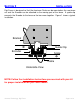
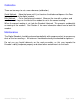
SECTION 2 INSTALLATION Digi Fence is designed so that the aluminum Scale can be mounted on the saw fence rail and the Encoder can be attached to the moving part of the fence. A guide clip connects the Encoder to the fence so the two move together. Figure 1 shows a typical installation. Bracket Guide Clip Encoder Scale Cable Underside View NOTE: Follow the Installation Instructions you received with your kit for proper installation on your fence model.
Calibration There are two ways to set a zero reference (calibration). Quick Method: Move the fence until it just touches the blade and depress the Zero key on the front of the digital readout. Best Method: Cut a small piece of material. Measure the size with a caliper, and use the + and - keys on the front of the readout to set in the correct reading. When the correct reading is set, lock the Readout if desired. This prevents accidentally re-zeroing of the readout.
SECTION 3 OPERATION Readout Keys Timing The keys pictured above have multiple functions. Timing, that is how long a key is depressed, and the combination of the keys pressed, is important. This manual uses the term ‘”momentarily” to describe a key press of typically less than 1 second. Whereas “press and hold” is used imply a key press of typically longer than 1.5 seconds.
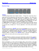
When the measurement is greater than 99 63/64 inches, a +100 and/or +200 will illuminate in the upper right portion of the display to indicate this amount must be added to the displayed reading. ie: If the measurement is 151 39/64 inches, 51 39/64 and +100 will be illuminated on the display. See photo below. +, 0, and – Keys The + (plus), 0 (zero) and – (minus) keys are used to change the currently displayed position to a different value. The 0 key forces the unit to display 0.
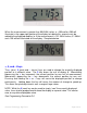
Display Resolution The Digital Readout can be configured to display measurements with different resolution. In Normal display mode the resolution is: .01in or .01mm. In Higher display mode the resolution is: .001in or .01mm In Lower display mode the resolution is: .1in or .1mm. Fractions remain the same for all settings: 1/16, 1/32 & 1/64 See Programming Parameter Pr4 Incremental Measurements To make Incremental measurements, press and hold MODE key for approximately 3 seconds.
Changing the Batteries A “BAT” indicator will appear in the upper left corner of the LCD display when new batteries are needed. Remove the screws in the upper right and lower left corners. Pull the cover off. Remove the old batteries. Reinstall new AA Alkaline batteries, noting the proper orientation. Replace the cover and tighten the screws.
Jumpers User configurable jumpers consist of three pins and a ‘shorting block’. The center of these pins is ‘Common’. One end pin is labeled ‘A’ and the other end pin is labeled ‘B’.
Programming Several functions of this Digital Readout are user programmable. The following describes how to change the factory defaults to customize your Digital Readout. To enter Programming Mode: 1. 2. 3. 4. Press and hold the MODE key then momentarily press the 0 key. The LCD will briefly display: pg on (Programming On), then Pr 1, (indicating Programming Parameter #1). Release the MODE key. The value stored for Pr1 is displayed.
Programming Parameters Programming Parameters are listed below. Values in [ ] are the available range of values that can be programmed for that parameter. Factory defaults are shown in Bold Red. Pr 1: 0 Key Value [0 to + 999.999in] or [0 to +9999.99mm] The programmed value that will be recalled whenever the 0 (zero) key is pressed during normal operation. Default = 0 Pr 2: Reverse Scaling [0 or 1] This parameter controls the sign of travel (positive vs negative) when the measuring system is moved.
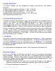
Frequently Asked Questions What F/W (Firmware) version do I have? The display will show d 2.xxx on power up. This is the firmware version of your Readout. What does “no Enc” mean? If the Encoder cable is unplugged from the Readout, no Enc will appear on the display. To clear: Be sure the Encoder is on the scale and plugged into the readout The keys don’t seem to do what they are supposed to do. Timing, that is how long a key is depressed, and the combination of the keys pressed is important.
Thank you for choosing an Accurate Technology Product Please register your system at: http://www.proscale.com/registration.htm Accurate Technology, Inc. 270 Rutledge Rd. Unit E Fletcher, NC 28732 USA 800 233-0580 • 828-654-7920 Fax 828-654-8824 www.digi-kit.com customerservice@accurate-technology.com This manual is available online at www.digi-kit.com P/N 800-1100-001 Rev.