ProScale Model 18W Limited Edition Model 18W ®
WARRANTY Accurate Technology, Inc. warrants the ProScale Model 18W against defective parts and workmanship for 1 year commencing from the date of original purchase. Upon notification of a defect, Accurate Technology, Inc., shall have the option to repair or replace any defective part. Such services shall be the customer's sole and exclusive remedy. Expenses incidental to repair, maintenance, or replacement under warranty, including those for labor and material, shall be borne by Accurate Technology, Inc.
Table of Contents SECTION 1 GENERAL INFORMATION..................................................4 INTRODUCTION............................................................................................4 ABOUT THIS MANUAL...................................................................................4 SPECIFICATIONS .........................................................................................4 SPECIFICATIONS ..................................................................................
SECTION 1 GENERAL INFORMATION Introduction ProScale is a general purpose linear measuring system consisting of three major parts: a SCALE, an ENCODER and a DIGITAL READOUT. ProScale is an ideal choice for most measuring requirements up to 8 inches where affordable digital precision (better than a tape measure) is desired.
Specifications Measuring Range*: up to 8 inches Accuracy: ± .003 inches Readout Resolution .1inch .1mm or .01inch .01mm or .001inch .01mm or 1/16, 1/32 or 1/64 inch Repeatability: .001inch or .01mm Readout Range: + 999.999 in; + 399 63/64 in; + 9999.
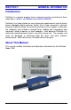
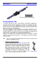
About ProScale Model 18W ProScale Model 18W is a Limited Edition 20th Anniversary Model sold exclusively on www.proscale.com and at Industry Trade shows where Accurate Technology exhibits. ProScale Model 18W systems consist of a READOUT (or DRO). SCALE, an ENCODER and a DIGITAL Scale DigiScale Model 18W The scale consists of a series of conductive patterns bonded to an aluminum extrusion. The Model 18W Scale is .765 inches wide and comes in measuring lengths up to 8 inches long.
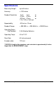
SECTION 2 INSTALLATION End view of Model 18W ProScale ProScale Model 18W The Model 18W can be used in many different measurement applications, and with numerous types of equipment. Therefore all installations will be a little different and it is the responsibility of the user to choose the bolts, screws, or other mounting hardware that provides a quality installation and optimum operation in their application.
2. Stationary Scale installation If your application is better suited for the scale to be held stationary and the encoder moved along it during a measurement, you should use the Guide Clip to capture the encoder and move it along the scale (see illustration). Attach the scale to a fixed point in your application using the included screw. Place the encoder on the scale.
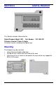
SECTION 3 DIGITAL READOUT This Section includes information for: Digital Readout, Model 18W Part Number: 700-1600-231 Firmware Version P 3xxxx & higher (Firmware version is displayed on power-up) Mounting The Readout may be mounted: • Using Velcro or Double sided tape • Drilling out the 3 holes from the inside of the case • Using any of the six holes on the back of the case which may tapped for M2 or 4-40 screws.
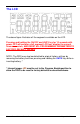
The LCD The above figure illustrates all the segments available on the LCD Pressing and holding the ON/OFF and UNITS key for 10 seconds with power OFF will perform a full segment LCD test, display the current firmware version, AND RESET ALL PROGRAMMING PARAMETERS TO FACTORY DEFAULT VALUES. NOTE: The DRO may also be defaulted to original factory settings by removing the battery and then pressing and holding the UNITS key while reinserting battery.
Fundamental Operation The following operations & functions apply to the Model 18W Digital Readout. KEY TIMING The keys pictured below have multiple functions. Timing (how long a key is depressed) is important. This manual uses the term “momentarily” to describe a key press and release of less than .8 seconds. Whereas “press and hold” is used to describe a key press and release of 1 second or longer. See Table Below: Momentarily Press & Hold How long a key is pressed? Less than .
Key Functions for standard operation ON/OFF KEY Momentarily press Momentarily press the ON/OFF key to turn DRO off then momentarily press it again to turn it back on. The Firmware version is displayed for two seconds at power-on. UNITS KEY Momentarily press Momentarily depressing the UNITS key will display measurement/position information in inches, fractions or millimeters . With each key press, the DRO will cycle through decimal inches, fractions (16ths, 32nds, 64ths) and millimeters.
PLUS (+) & MINUS (–) KEYS Momentarily or Press & Hold Momentarily depressing the + or – key increments or decrements the current displayed value by one unit of measurement. Pressing and holding the + or – key will cause the displayed value to change continuously. Continue pressing the key to cause the amount of change to speed up. This allows for quick adjustments over a large range of values. These keys may be locked out to prevent accidental offset entries.
Basic Functions MEASUREMENT READING DIRECTION Once the system has been put into operation, if the direction of readings, (positive or negative values) is opposite the desired direction, the DRO programming may be changed to correct the direction. See Programming Parameter (Pr2). KEY LOCK The Digital Readout provides a function that can be used to “lock-out” the position offset adjustment keys (+, DATUM , –) to prevent accidental changes of the current displayed value.
Changing the Batteries A low battery indicator will appear in the lower left corner of the LCD. Press and hold DATUM key for 6 seconds to display the Battery Voltage. When battery voltage drops below approximately 2.6V the DRO will turn itself off until the batteries are replaced. To replace the battery: Remove the screws in the upper right and lower left corners. Pull the cover off. Remove the old batteries. Reinstall 2 new AA Alkaline batteries, noting the proper orientation.
Circuit Board Jumpers JP1 FACTORY USE ONLY JP2 FACTORY CONFIGURED: DO NOT CHANGE JP3 Programming Lock-out Default = Position A Front panel programming of the Digital Readout can be enabled or disabled though the use of this circuit board jumper. Front panel Programming is enabled when the shorting jumper is installed in position A. To disable Programming, install jumper on position B.
SECTION 4 PROGRAMMING Several functions of the Readouts are user programmable. The following section describes how to change factory defaults to customize your DRO. To enter Programming Mode: 1. Press and hold the UNITS key then momentarily press the DATUM key. 2. The LCD will briefly display: PG on (Programming On), then Pr 1, 1 (indicating Programming Parameter #1) 3. Release the UNITS key 4. The value stored for Pr1 is displayed.
The Digital Readout Programming Parameters are listed below. Values in [ ] are the range of values available for that Parameter. Factory defaults values are shown in Bold Red. Pr 1 – Datum Key [0 to + 999.999in] or [0 to +9999.99mm] The programmed value that will be recalled whenever the Datum key is pressed during normal operation. Default = 0.00 Pr 2 – Direction of Travel [0 or 1] This parameter controls the sign of travel (positive vs. negative) when the measuring system is moved.
Frequently Asked Questions Can I mount the Scale/Encoder without the connector link/guide clip? Yes. However, the connector link and guide clip serve to provide an accurate method of transferring the movement of the encoder or scale, while also absorbing any stresses that may occur. If they are not used, your system could be damaged and the warranty could be voided. What does no Enc mean? If the encoder is off the scale, or unplugged from the readout, a no Enc will appear on the readout.
Thank you for choosing an AMERICAN MADE PRODUCT Accurate Technology, Inc. 270 Rutledge Rd. Unit E Fletcher, NC 28732 USA 828.654.7920 Please register your product at: http://www.proscale.com/registration.htm This manual is available online at: www.proscale.com Part # 800-1405-001, Rev A Copyright © 2010 Accurate Technology, Inc. All rights reserved.