
User's Manual


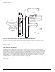


Table Of Contents
- Contents
- Preface
- Altitude 300-2TM Wireless Port Introduction
- HARDWARE INSTALLATION
- SPECIFICATIONS
- Maximum Distance Table
- Integrated Dual Band Antenna Pattern
- COMPLIANCES
- Power Over Ethernet Connector Pin Assignments
- Ethernet Connector Pin Number Assignment

BETA DRAFT
Altitude 300-2 Getting Started Guide 11
WARNING!
The Altitude 300-2
™
is not designed for outdoor use or sites that exceed its environmental
specifications.
Mounting Below A Hard Ceiling
The Altitude 300-2
™
may be installed underneath a hard ceiling where wall anchors are used to mount
the bracket. Select the orientation for the bracket remembering that that integrated antennas are on the
side and to the back of the Altitude 300-2i
™
. Use the bracket as a template to mark the holes on the
ceiling. For each of the four plastic anchors supplied with the unit, drill 4.8 mm (3/16"} pilot holes, 24.5
mm (1") deep. If wall anchors are not being used drill 3.2 mm (1/8") holes, 1 inch (25.4 mm) deep.
Install the bracket using the screws from the kit. The Altitude 300-2
™
is designed to slip into the
mounting slots on the bracket and slide all the way to the front, see Figure 5: Mounting The Wireless
Port On The Universal Mounting Bracket on page 14. The unit should then be secured with either a
padlock (not supplied) or a cable tie (supplied). The installer may now follow the standard instructions
for connecting the Ethernet cable, antenna shrouds for integrated antennas, and the plastic cover.
WARNING!
The Altitude 300-2
™
is not secured to the bracket unless a padlock is used. If a padlock is not used the
unit should be secured to the bracket by a cable tie through the lock hasp to keep it from falling. Failure
to secure the unit is hazardous.
Mounting Below A Hanging Ceiling
The Altitude 300-2
™
may be suspended from the T-Bars of a hanging ceiling. The mounting kit contains
two T-Bar fasteners that can be adjusted for a variety of T-Bar widths. There are a number of round
holes on the bracket that can be used for the T-Bar fasteners; use two that are convent for the required
orientation on the ceiling. The bracket is oriented on the T-Bar with so that the antennas face the desired
direction. Use the bracket to lightly mark where the T-Bar fasteners should be placed. Install the two
T-Bar fasteners on the T-Bar, see Figure 6: Installation On A Hanging Ceiling on page 15. Some ceilings
have ceiling tiles that hang down below the bottom of the T-Bar. Spacers are provided with the kit for
these types of tiles. The spaces go between the T-Bar fasteners and the bracket with the spacer's face
against the bracket, see Figure 7: Installation Of Optional Spacer on page 15. Mount the bracket and
make sure fasteners are tight and the bracket is secure. The Altitude 300-2
™
is now slipped into the
bracket's mounting slots and slid all the way to the back, see Figure 5: Mounting The Wireless Port On
The Universal Mounting Bracket on page 14. The unit should then be secured with either a padlock (not
supplied) or a cable tie (supplied). The installer may now follow the standard instructions for
connecting the Ethernet cable, antenna shrouds for integrated antennas, and the plastic cover.
WARNING!
The Altitude 300-2
™
is not secured to the bracket unless a padlock is used. If a padlock is not used the
unit should be secured to the bracket by a cable tie through the lock hasp to keep it from falling. Failure
to secure the unit is hazardous.
Mounting Above The Hanging Ceiling
The Altitude 300-2d
™
is compliant with UL 2043 for installation in the plenum area above a hanging
ceiling. The installer needs to make sure that the Ethernet cable used to connect to the unit is also