
User's Manual


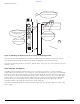


Table Of Contents
- Contents
- Preface
- Altitude 300-2TM Wireless Port Introduction
- HARDWARE INSTALLATION
- SPECIFICATIONS
- Maximum Distance Table
- Integrated Dual Band Antenna Pattern
- COMPLIANCES
- Power Over Ethernet Connector Pin Assignments
- Ethernet Connector Pin Number Assignment

BETA DRAFT
6 Altitude 300-2 Getting Started Guide
HARDWARE INSTALLATION
Figure 6: Mounting The Wireless Port On The Universal Mounting Bracket
To remove the wireless port from the universal mounting bracket first unlock or remove the cable tie.
Push the box in the direction of the lock hasp while gently lifting it away from the bracket.
The universal mounting bracket is part of the Altitude 300-2
™
kit. Spares may also be ordered. The part
number is 15921.
T-Bar Fasteners and Spacers
The T-Bar fasteners included with the wireless port are designed to connect to a range of hanging
ceiling T-Bar sizes. Following the steps in Figure 6, spread the T-Bar fastener apart, place it on the T-Bar
and squeeze it together until it is firmly seated on the T-Bar. With the two T-Bar fasteners in place and
properly spaced to match the brackets T-Bar fastener holes, determine if spacers are needed. The T-Bar
fastener spacers are designed for hanging ceilings where the ceiling tiles' bottom surface is bellow the
T-Bar. If this is the case, install the spacer as show in the diagram. The spacer allows the universal
mounting bracket to sit below the bottom surface of the ceiling tile.
The universal mounting bracket is installed using the large wing nuts provided. Make sure these wing
nuts are tight.
(1) Locate the three mounting
holesonthebackofthebox
(2) Insert the bracket’s
mounting studs into the
mounting holes
(3) Firmly slide the
box down on the studs
(4) The box is properly
installed when the lock
hasp holes are lined up