
User's Manual


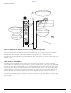


Table Of Contents
- Contents
- Preface
- Altitude 300-2TM Wireless Port Introduction
- HARDWARE INSTALLATION
- SPECIFICATIONS
- Maximum Distance Table
- Integrated Dual Band Antenna Pattern
- COMPLIANCES
- Power Over Ethernet Connector Pin Assignments
- Ethernet Connector Pin Number Assignment

BETA DRAFT
4 Altitude 300-2 Getting Started Guide
HARDWARE INSTALLATION
NOTE
While the Altitude 300-2
™
uses standard a standard 10/100BaseT signal and PoE power, it should only
be connected to a Summit 300-48
™
port for the proper operation of the management and configuration
features of Extreme Networks’ Unified Access System.
6 Connect the computer cable lock (optional). When the Altitude 300-2
™
installation does not use the
universal mounting bracket, the unit can be locked with a computer cable. The Altitude 300-2
™
has a
standard computer cable lock hole located at the rear of the box, see Figure 1: Rear View Of Altitude
300-2i
™
on page 7, or Figure 2: Rear View Of Altitude 300-2d
™
on page 8.
7 Connect the external antennas, Altitude 300-2d
™
. For the Altitude 300-2i
™
skip to step 8. The
Altitude 300-2dO has connectors for external antennas, see Figure 2: Rear View Of Altitude 300-2d
™
on page 8. The access unit should be located within the reach of the antenna's cables. The large
RP-TNC connectors are used for 2.4 GHz 802.11b/g antennas and the small RP-SMA connectors for 5
GHz 802.11a antennas. Two connectors of each type are supplied to support spatial diversity. The
unit can be operated with one antenna on each radio if desired. When this step is completed go to
step 10.
8 Attach the antenna shrouds (Altitude 300-2i
™
) - If the plastic cover is going to be used attach the
antenna shrouds to the antennas, see Figure 8: Antenna Shroud on page 16.
9 Adjust the Integrated antennas, Altitude 300-2i
™
- The Altitude 300-2i
™
is equipped with two
integrated dual band antennas that connect to both the 802.11a and 802.11b/g radios. Selecting the
proper angle for the antennas is important to achieve the best performance from the system. For this
reason the Altitude 300-2i
™
is equipped with antennas that can be rotated. Once the proper angle has
been set the Altitude 300-2i
™
is outfitted with antenna shrouds that work with the plastic cover to
lock in the proper angle. This to prevents the antennas from being accidentally misaligned after
installation.
10 Attach the plastic cover -Attach the optional plastic cover to the box, see Figure 10: Plastic Cover
Installation on page 17. After the cover has been secured push on each antenna to make sure is
shroud is locked in position. This ensures that the teeth on the shroud are engaged with the teeth on
the cover.
WARNING!
Attach the plastic cover -Attach the optional plastic cover to the box, see Figure 10: Plastic Cover
Installation on page 17. After the cover has been secured push on each antenna to make sure is
shroud is locked in position. This ensures that the teeth on the shroud are engaged with the teeth on
the cover.
Altitude 300-2
™
and Mounting Hardware
Before starting to install the wireless port and its hardware, take time to become familiar with the parts
and their physical features.
Universal Mounting Bracket
The universal mounting bracket included with the wireless port is designed to mount on vertical and
horizontal surfaces like walls and ceilings. It can be attached to electrical junction boxes in place of a
wall plate and the Ethernet cable routed from the wall or ceiling through the central hole in the bracket
to the Altitude 300-2
™
’s Ethernet jack. The universal mounting bracket can also be directly attached to a
solid surface and the Ethernet cable attached through the network cable hole in the rear of the plastic