
User's Manual


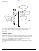


Table Of Contents
- Contents
- Preface
- Altitude 300-2TM Wireless Port Introduction
- HARDWARE INSTALLATION
- SPECIFICATIONS
- Maximum Distance Table
- Integrated Dual Band Antenna Pattern
- COMPLIANCES
- Power Over Ethernet Connector Pin Assignments
- Ethernet Connector Pin Number Assignment

Altitude 300-2 Getting Started Guide 3
BETA DRAFT
2 HARDWARE INSTALLATION
Installation Steps
1 For wall and ceiling installations the universal mounting bracket is used. If unit is being mounted on
a table or shelf skip to step 4. Locate and install the universal mounting bracket. Refer to the
instructions for the various ceiling installation options (Mounting Below A Hard Ceiling page 18,
Mounting Below A Hanging Ceiling: page 18, Mounting Above The Hanging Ceiling: page 18, and
Mounting Above The Hanging Ceiling: page 19) and the wall mounting option (Mounting On A Wall:
page 20) in the next section.
2 Mount the Altitude 300-2
™
on the universal mounting bracket. The Altitude 300-2
™
has three slotted
mounting holes on the back of the unit. The mounting studs on the universal mounting bracket fit
into the slotted mounting holes. The unit slides all the way forward into these holes. The lock hasp
hole on the Altitude 300-2
™
should line up with the lock hasp hole on the universal mounting
bracket when the unit is slid all the way forward, see Figure 5: Mounting The Wireless Port On The
Universal Mounting Bracket on page 14.
3 Lock and secure the Altitude 300-2
™
. The Altitude 300-2
™
and the universal mounting bracket are
designed to use a Master Lock 120T or similarly sized padlock to secure the wireless port from theft
of from coming off the bracket, see Figure 5: Mounting The Wireless Port On The Universal
Mounting Bracket on page 14. Wall and ceiling installations skip step 4.
WARNING!
The Altitude 300-2
™
is not secured to the bracket unless a padlock is used. If a padlock is not used the
unit should be secured to the bracket by a cable tie through the lock hasp to keep it from falling. Failure
to secure the unit is hazardous.
4 For table and shelf installations, attach the stick-on feet. The Altitude 300-2
™
kit comes with four
stick-on feet for use when the unit is installed on top of a table or shelf. The feet do not have to be
used for wall and ceiling installations.
WARNING!
The stick-on feet have not been tested for use in a plenum space. Do not use them for above the ceiling
installations.
5 Connect the Ethernet Cable - The Altitude 300-2
™
is connected to a powered, 10/100BaseT Ethernet
cable from a Summit 300-48
™
.