
Switch User Manual
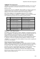


Cables
B-2
10BASE-T/100BASE-TX Pin Assignments
For 100BASE-TX/10BASE-T connections, a twisted-pair cable must have two pairs
of wires. Each wire pair is identified by two different colors. For example, one wire
might be red and the other, red with white stripes. Also, an RJ-45 connector must be
attached to both ends of the cable.
With 100BASE-TX/10BASE-T cable, pins 1 and 2 are used for transmitting data, and
pins 3 and 6 for receiving data.
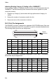
Because all ports on this switch support automatic MDI/MDI-X operation, you can
use straight-through cables for all network connections to PCs or servers, or to other
switches or hubs. In straight-through cable, pins 1, 2, 3, and 6, at one end of the
cable, are connected straight through to pins 1, 2, 3 and 6 at the other end of the
cable. The table below shows the 10BASE-T/100BASE-TX MDI and MDI-X port
pinouts.
Note: Auto-negotiation must be enabled for automatic MDI/MDI-X pinout configuration.
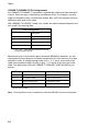
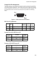
RJ-45 Pin Assignments
Pin Number
Assignment
1
1Tx+
2Tx-
3Rx+
6Rx-
1: The “+” and “-” signs represent the polarity of the wires
that make up each wire pair.
Pin MDI-X Assignment MDI Assignment
1 Input Receive Data + Output Transmit Data +
2 Input Receive Data - Output Transmit Data -
3 Output Transmit Data + Input Receive Data +
6 Output Transmit Data - Input Receive Data -
No other pins are used.