
Switch User Manual

4-1
Chapter 4: Making Network Connections
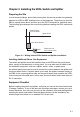
Twisted-Pair Devices
Each device requires an unshielded twisted-pair (UTP) cable with RJ-45 connectors
at both ends. For 100BASE-TX connections, Category 5 cable is required; for
10BASE-T, Category 3, 4 or 5 cable can be used.
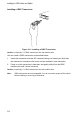
Cabling Guidelines
The RJ-45 ports on the switch support automatic MDI/MDI-X operation, so you can
use standard straight-through twisted-pair cables to connect to any other network
device (PCs, servers, switches, routers, or hubs).
Note: Auto-negotiation must be enabled for automatic MDI/MDI-X pinout configuration.
See Appendix B for further information on cabling.
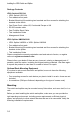
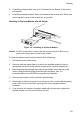
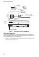
Connecting to the Punch-down Blocks
The splitter connects directly to the PBX and building’s phone-line punch-down
block with RJ-21 connectors. Follow the steps listed below to connect the splitter.
1. Connect one RJ-21 flat cable from the PBX/MDF to the RJ-21 connector on the
back of the splitter labeled “PBX.”
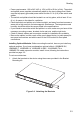
2. Connect the other RJ-21 flat cable from the punch-down block to the RJ-21
connector on the front of the splitter labeled “Line.”
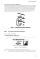
The RJ-21 port on punch-down blocks must be wired to match the pin assignments
of ports on the back of the splitter. To ensure that your cables are properly wired,
refer to “RJ-21 Port Pin Assignments” on page B-4.
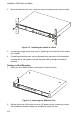
Note: If you are using a patch panel, connect the RJ-21 ports on the back of the splitter
directly to the corresponding ports on the patch panel, and then manually wire
each pair (up to 24) from the patch panel to the punch-down blocks.