Accel Instruments User’s Manual TS200 Modulated Power Supply Battery Simulator/Emulation Waveform Amplifier Power/Current Amplifier PSRR/CMRR Measurement Voltage Supply Transient Measurement 1
Warranty Information Accel Instruments, LLC (hereon referred to as Accel Instruments) warrants this product for a period of one (1) year from date of shipment. If the device is defective within the warranty period, Accel Instrument will either repair or replace the product. Warranty is voided if the device is opened by anyone other than Accel Instruments. Warranty Limitations This warranty does not apply to normal wearing or misuse of the product or part.
Safety Precautions Output voltage is up 72VDC. To avoid the risk of electrical shock, use proper safety techniques when operating this device. Avoid touching any part of the non-insulated output connection during operation. Avoid the risk of electrical shock, do not open the device. Caution: The TS200 heatsink may be hot. Avoid touching the heatsink.
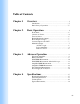
Table of Contents Chapter 1 Overview……………………….…………………………….5 Introduction………………………………………..……....5 Basic theory of operation……………....……………….....5 Chapter 2 Basic Operation……………………………….…………6 Front Panel…………………………….………..…………6 Connect AC Power………………….…………..…………6 Turn On Power………………………………….…………6 Enable/Disable the Output………………..…….…………7 Preset Output Voltage…………………………..…………7 Connect Output to the DUT…………………….……....…7 Modulation Input…………………….……………….....…7 AC/DC Couple…………………….……....
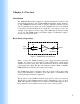
Chapter 1: Overview Introduction The TS200 Modulated Power Supply is a unique instrument for many test and measurement applications such as LDO PSRR measurement, battery simulator, op amp CMRR measurement, function generator amplifier, transient response test, four-quadrant power supply, lab power amplifier and more. It is designed for bench test and measurement. It can output DC or AC voltage or both. For example, it can output a 3.3V DC voltage with a 300mVpp AC sinewave riding on top of it.
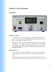
Chapter 2: Basic Operation Front Panel Connect AC Power Connect the AC power cord (included) to the TS200 first. Then plug the AC power cord to the wall outlet. The TS200 input is universal and can accept 100V to 230V, 50Hz and 60Hz, line voltage. Warning: The AC power cord included in the TS200 is for North American wall plug only. It is equipped with 3-wire grounding connection. The TS200 must be plug-in into a 3-wire outlet with proper grounding.
Enable/Disable the Output Press the ON/OFF button to enable the output. The ON/OFF button will lite with a green light. Press the ON/OFF button again will disable the output. The output is high-Z when disabled. Warning: To avoid the risk of electrical shock, always disable the output before making wire connections. While the output is enabled, avoid physical contact with any non-insulated electrical connections.
AC/DC Couple The modulation input can be AC or DC coupled. Remember the output voltage is the superimposed of OFFSET voltage and MODULATION voltage. Power Amplifier The TS200 can be used as a current or power amplifier. The modulation input serves as amplifier input. The TS200 offers 0dB and 20dB gain options. Remote Control The MODULATION input can serve as a remote voltage setting. To do so, adjust the OFFSET knob until the voltage reaches 0.
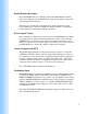
Chapter 3: Advance Operation Waveform Amplifier Function Generator Or AWG Mod Input Output TS200 Figure 2. Waveform amplifier setup The TS200 is also ideal for amplifying waveforms for driving high-voltage or high current or both. It is ideal for amplifying function generator output to drive heavy load. TS200 is ideal for laboratory power amplifier. Figure 2 shows the TS200 connection as a high voltage or power amplifier.
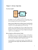
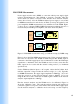
LDO PSRR Measurement Power supply rejection ratio (PSRR) or some time called power supply ripple rejection measurement are often difficult to measure, especially when the device under test (DUT) is heavily loaded. Because most network analyzer cannot drive a heavy load, the TS200 modulated power supply is very useful for PSRR measurement for such devices as LDOs (low dropout regulators) and power amplifiers. PSRR measurement is easy with the aid of the TS200. Figure 3 shows how to measure PSRR.
range (i.e. 100Hz to 100kHz) to be measured. Save the calibration data for later use. Refer the network analyzer manual for detailed calibration setup. PSRR (dB) After calibration, LDO PSRR measurement setup is shown Figure 3b. The network analyzer input-B is moved to the LDO output near the capacitor while keeping input-A at the LDO input. Again sweep the network analyzer over the desired frequency range. You may refer to the network analyzer manual for details.
Function Generator Or AWG Mod Input Output LDO Load TS200 DUT CH1 Oscilloscope CH2 Figure 5. PSRR measurement using an oscilloscope. Using the oscilloscope, one can measure the amplitude voltage at CH1 and CH2. Divide CH2 by CH1 is the PSRR. One can use the below equation for PSRR calculation in dB. PSRR = 20log(CH2/CH1) If PSRR is better than 40dB, it is recommended to increase the TS200 output ripple voltage to 500mVpp due to oscilloscope has lower sensitivity than network analyzer.
Source Network Ananyzer Mod Input Output DUT TS200 A Load B (a) Source Network Ananyzer Mod Input Output DUT TS200 Load A B (b) Figure 6. PSRR measurement setup for amplifier. (a) Calibration setup, (b) PSRR setup. As shown in Figure 6, the amplifier input is grounded, either AC or DC ground, for PSRR measurement. Calibrate the setup as shown in Figure 6a with the network analyzer input-A and input-B connected to the same point at the amplifier’s supply input.
Amplifier CMRR Measurement Amplifier common-mode rejection ratio or CMRR can be measure with TS200. Figure 7 shows how to measure CMRR. CMRR measurement for amplifiers is same as PSRR except for a few minor differences. DUT Source Network Ananyzer Mod Input Output Load TS200 A B (a) DUT Source Network Ananyzer Mod Input Output Load TS200 A B (b) Figure 7. CMRR measurement setup for amplifier. (a) Calibration setup, (b) CMRR setup.
Line Transient Measurement Function Generator Or AWG Mod Input Output LDO/SMPS Load TS200 DUT CH1 Oscilloscope CH2 Figure 8. Line transient measurement setup. Most LDOs and switch-mode power supply (MSPS) specified their line transient specifications. Line transient response specifies its output voltage change after an input voltage step change. For example, an LDO specified its output voltage deviates less than 5mV for a 200mV input voltage step from 3.6V to 3.8V in 10 microseconds.
Figure 9. Line transient measurement example. Power Supply Noise Injector Function Generator Or AWG Mod Input Output TS200 Figure 10. Power supply noise simulator In some applications, the device under test may be sensitive to power supply noise. For example, VCO (voltage controlled oscillator) phase noise may be degraded with excessive supply noise. The TS200 can be used to aid supply noise sensitive circuit testing. Figure 10 shows a supply noise simulation setup.
` Chapter 4: Specifications Electrical Specifications Parameter Output Voltage Range Continues Output Current Modulation Input Voltage Range Modulation Gain Min Modulation Frequency Max Modulation Frequency Slew Rate LCD Voltmeter Accuracy Condition/Note TS200-0 TS200-1 TS200-2 TS200-3 TS200-4 TS200-5 See Typical Performance Curves DC Non-inverted -3dB, no load -3dB, no load, small signal Midrange A-version B-version AC-Coupled DC-Coupled AC-Coupled DC-Coupled MIN TYP MAX -10 +10 -20 +20 -20 +45 -10 +7
TS200 Options Options TS200-0A TS200-0B TS200-1A TS200-1B TS200-2A TS200-2A TS200-3A TS200-3B TS200-4A TS200-5A TS200-5B Output Voltage Range -10V to +10V -10V to +10V -20V to +20V -20V to +20V -20V to +45V -20V to +45V -10V to +70V -10V to +70V 0V to +15V -40V to +40V -40V to +40V Modulation Gain (V/V) Output Current +1 +10 +1 +10 +1 +10 +1 +10 +1 +1 +10 See Typical Performance Curves 18
Typical Performance 19
Typical Performance 20
Accel Instrumentsl Email: info@accelinstruments.com Website: www.accelinstruments.