
User`s manual
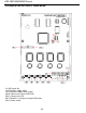
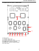

Chapter 4 PCB Layout
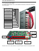
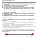
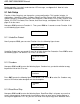
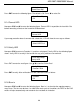
The layout of the ARS-2057 is shown below.
13
J4: USB signal link
J9: ATX power supply socket
J10: ATX power supply switch socket
CN10: Connects to source DVD-ROM
CN12: Connects to HDD
CN7-CN6&CN11: Connects to target DVD writers
CN13: Power socket
CN7
Red
CN10
CN12
J8
J10
CN13
CN6 CN7 CN9 CN8 CN11
J4
ARS-2057/2050/2050P Manual