SMVector - Frequency Inverter Operating Instructions
Contents 1 Safety Information..................................................................................................... 3 2 Technical Data........................................................................................................... 6 2.1 2.2 2.3 3 Installation............................................................................................................... 11 3.1 3.2 4 Dimensions and Mounting.......................................................................
About These Instructions This documentation applies to the SMV frequency inverter and contains important technical data regarding the installation, operation, and commissioning of the inverter. These instructions are only valid for SMV frequency inverters with software revision 4.0 or higher (refer to drive nameplate, an example is shown below). Please read these instructions in their entirety before commissioning the drive. A B C D INPUT: 3 (3/PE) 400/480 V 2.9/2.
Safety Information 1 Safety Information General Some parts of Lenze AC Tech controllers can be electrically live and some surfaces can be hot. Non-authorized removal of the required cover, inappropriate use, and incorrect installation or operation creates the risk of severe injury to personnel and/or damage to equipment.
Safety Information Explosion Proof Applications Explosion proof motors that are not rated for inverter use lose their certification when used for variable speed. Due to the many areas of liability that may be encountered when dealing with these applications, the following statement of policy applies: Lenze AC Tech Corporation inverter products are sold with no warranty of fitness for a particular purpose or warranty of suitability for use with explosion proof motors.
Safety Information Harmonics Notification in accordance with EN 61000-3-2, EN 61000-3-12: Operation in public supply networks (Limitation of harmonic currents i.a.w. EN 61000-3-2, Electromagnetic Compatibility (EMC) Limits). Limits for harmonic current emissions (equipment input current up to 16A/phase). Directive Total Power connected to Mains (public supply) Additional Measures Required for Compliance (2) < 0.5kW with mains choke EN 61000-3-2 0.5 ...
Technical Data 2 Technical Data 2.1 Standards and Application Conditions Conformity CE Low Voltage (2006/95/EC) & EMC (2004/108/EC) Directives Approvals UL508C Underwriters Laboratories -Power Conversion Equipment Input voltage phase imbalance < 2% −− For central grounded systems, operation is permitted without restrictions. −− For corner grounded 400/500V systems, operation is possible but reinforced insulation to control circuits is compromised.
Technical Data 2.2 SMV Type Number Designation The table herein describes the Type numbering designation for the SMVector Inverter models. ESV 152 N0 2 T X B Electrical Products in the SMVector Series Power Rating in kW: 251 = 0.25kW (0.33HP) 371 = 0.37kW (0.5HP) 751 = 0.75kW (1HP) 112 = 1.1kW (1.5HP) 152 = 1.5kW (2HP) 222 = 2.2kW (3HP) 302 = 3.0kW (4HP) 402 = 4.0kW (5HP) 113 = 11.0kW (15HP) 153 = 15.0kW (20HP) 183 = 18.5kW (25HP) 223 = 22.0kW (30HP) 303 = 30.0kW (40HP) 373 = 37.
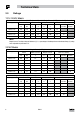
Technical Data 2.3 Ratings 120V / 240VAC Models Mains = 120V Single Phase (1/N/PE) (90...132V), 240V Single Phase (2/PE) (170...264V); 48...62Hz Type Power Mains Current Output Current Heat Loss (Watts) Hp kW 120V A 240V A Cont (In) A Max I % N1/IP31 N4X/IP65 N4X/IP65 No filter W/ filter ESV251--1S-- 0.33 0.25 6.8 3.4 1.7 200 24 ESV371--1S-- 0.5 0.37 9.2 4.6 2.4 200 32 32 ESV751--1S-- 1 0.75 16.6 8.3 4.2 200 52 41 ESV112--1S-- 1.5 1.1 20 10.0 6.
Technical Data 240V Three Phase (3/PE) (170...264V); 48...62Hz Type Power Mains Current Output Current Heat Loss (Watts) Cont (In) A Max I % N1/IP31 64 Hp kW 240V A ESV112--2T-- 1.5 1.1 6.9 6 200 ESV152--2T-- 2 1.5 8.1 7 200 75 ESV222--2T-- 3 2.2 10.8 9.6 200 103 N4X/IP65 N4X/IP65 No filter W/ filter ESV402--2T-- 5 4.0 18.6 16.5 200 154 139 ESV552--2T-- 7.5 5.5 26 23 200 225 167 ESV752--2T-- 10 7.
Technical Data 600VAC Models 600V Three Phase (3/PE) (425...660V); 48...62Hz Type Power Mains Current Output Current Heat Loss (Watts) Max I % N1/IP31 A Cont (In) A N4X/IP65 N4X/IP65 No filter W/ filter Hp kW ESV751--6T-- 1 0.75 2 1.7 200 37 31 ESV152--6T-- 2 1.5 3.2 2.7 200 51 43 ESV222--6T-- 3 2.2 4.4 3.9 200 68 57 ESV402--6T-- 5 4 6.8 6.1 200 101 67 ESV552--6T-- 7.5 5.5 10.2 9 200 148 116 ESV752--6T-- 10 7.5 12.
Installation 3 Installation 3.1 Dimensions and Mounting WARNING! Drives must not be installed where subjected to adverse environmental conditions such as: combustible, oily, or hazardous vapors; corrosive chemicals; excessive dust, moisture or vibration; direct sunlight or extreme temperatures. 3.1.
Installation 3.1.2 NEMA 1 (IP31) Models > 30HP (22kW) c b2 b1 s2 b s1 s1 SMV SMV s2 a1 a Type a in (mm) a1 in (mm) b in (mm) b1 in (mm) b2 in (mm) c in (mm) s1 in (mm) s2 in (mm) m lb (kg) K1 ESV303~~4~~B; ESV303~~6~~B 8.72 (221) 7.50 (190) 14.19 (360) 13.30 (338) 0.45 (11.4) 10.07 (256) 0.6 (15) 2.0 (50) 24 (10.9) K2 ESV373~~4~~B; ESV373~~6~~B 8.72 (221) 7.50 (190) 17.19 (436) 16.30 (414) 0.45 (11.4) 10.07 (256) 0.6 (15) 2.0 (50) 31 (14.
Installation 3.1.3 NEMA 4X (IP65) Models b2 c s2 Mounting Screws 4 x #8 32 10 lb in 4 x M4 1 2 Nm ( ) b1 b s1 s1 s2 a1 a Type a in (mm) a1 in (mm) b in (mm) b1 in (mm) b2 in (mm) c in (mm) s1 in (mm) s2 in (mm) m lb (kg) ESV371N01SX_; ESV751N01SX_; ESV371N02YX_; ESV751N02YX_; ESV371N04TX_; ESV751N04TX_; ESV751N06TX_; ESV371N02SF_; ESV751N02SF_; ESV371N04TF_; ESV751N04TF_; 6.28 (160) 5.90 (150) 8.00 (203) 6.56 (167) 0.66 (17) 4.47 (114) 2.00 (51) 2.00 (51) 3.6 (1.
Installation 3.1.4 NEMA 4X (IP65) Models with Disconnect Switch b2 c1 c s2 Mounting Screws 4 x #8 32 10 lb in 4 x M4 1 2 Nm ( ) b1 s1 s1 b s2 a1 a a in (mm) a1 in (mm) b in (mm) b1 in (mm) b2 in (mm) c in (mm) c1 in (mm) s1 in (mm) s2 in (mm) m lb (kg) 6.28 (160) 5.90 (150) 10.99 (279) 9.54 (242) 0.66 (17) 4.47 (114) .86 (22) 2.00 (51) 2.00 (51) 4.7 (2.13) 6.28 (160) 5.90 (150) 10.99 (279) 9.54 (242) 0.66 (17) 6.31 (160) .86 (22) 2.00 (51) 2.00 (51) 7.9 (3.
Installation 3.2 Electrical Installation Installation After a Long Period of Storage STOP! Severe damage to the drive can result if it is operated after a long period of storage or inactivity without reforming the DC bus capacitors. If input power has not been applied to the drive for a period of time exceeding three years (due to storage, etc), the electrolytic DC bus capacitors within the drive can change internally, resulting in excessive leakage current.
Installation 3.2.1.2 Mains Connection to 240VAC Single-Phase Supply PE L1 L2 N PE L1 L2 N ESV...N01S... ESV...N01S... PE L1 L2 PE PE L1 L2 L3 ESV...N02Y... (1/N/PE AC) PE L1 L2 PE PE L1 L2 L1 N PE L1 L2 ESV...N02S... (2/PE AC) ESV...N02S... (1/N/PE AC) PE L1 L2 PE L1 N Mains Connection to Three-Phase Supply ESV...N02Y... ESV...N02T... ESV...N04T... ESV...N06T... (3/PE AC) PE L1 L2 L3 PE 3.2.1.4 N PE L1 L2 L3 ESV...N02Y... (2/PE AC) 3.2.1.
Installation 3.2.1.5 Installation Recommendations for EMC Compliance For compliance with EN 61800-3 or other EMC standards, motor cables, line cables and control or communications cables must be shielded with each shield/screen clamped to the drive chassis. This clamp is typically located at the conduit mounting plate. The EMC requirements apply to the final installation in its entirety, not to the individual components used.
Installation 3.2.1.7 Dynamic Brake Connections For NEMA 1 and NEMA 4X Drives rated up to 30HP (22kW) the Dynamic Brake connections are made as illustrated herein. Refer to the SMV Dynamic Brake Instructions (DBV01) for complete information. NEMA 1 (IP31) up to 30HP (22kW) NEMA 4X (IP65) up to 30HP (22kW) + - The SMV 40...60Hp (30...45kW) models include a dynamic brake transistor as standard and only require the connection of an external resistor kit for dynamic braking operation.
Installation 3.2.2 Fuses/Cable Cross-Sections NOTE: Observe local regulations. Local codes may supersede these recommendations Recommendations 120V 1~ (1/N/PE) 240V 1~ (2/PE) 240V 3~ (3/PE) 400V or 480V 3~(3/PE) 400V or 480V 3~(3/PE) 600V 3~(3/PE) Input Power Wiring (L1, L2, L3, PE) Fuse Miniature circuit breaker(1) Fuse (2) or Breaker(3) (N. America) ESV251N01SXB M10 A C10 A 10 A 1.5 14 ESV371N01SXB, ESV371N01SX* M16 A C16 A 15 A 2.
Installation Notes for Fuse and Cable Table: (1) Installations with high fault current due to large supply mains may require a type D circuit breaker. (2) UL Class CC or T fast-acting current-limiting type fuses, 200,000 AIC, preferred. Bussman KTK-R, JJN or JJS or equivalent. (3) Thermomagnetic type breakers preferred.
Installation Control Terminal Strip Descriptions Terminal Description Important 1 Digital Input: Start/Stop 2 Analog Common 5 Analog Input: 0...10 VDC input resistance: >50 kΩ 6 Internal DC supply for speed pot +10 VDC, max. 10 mA 25 Analog Input: 4...20 mA input resistance: 250Ω input resistance = 4.3kΩ 4 Digital Reference/Common +15 VDC / 0 VDC, depending on assertion level 11 Internal DC supply for external devices +12 VDC, max.
Commissioning 4 Commissioning 4.1 Local Keypad & Display SMV Models: 0.33-10HP (0.25-7.5kW) AUTO SMV Models: 15HP (11kW) and greater FWD REMOTE LOCAL CTRL MAN AUTO RPM Hz % AMPS /UNITS REV RUN AUTO FWD REV RUN STOP STOP 4-Character Display Display 4-Character plus CTRL Display START BUTTON In Local Mode (P100 = 0, 4, 6), this button will start the drive. RUN STOP BUTTON Stops the drive, regardless of which mode the drive is in.
Commissioning Display INDICATING LEDs (on 4-character display) FWD FWD LED: Indicate the present rotation direction is forward. Refer to ROTATION description above. REV LED: Indicate the present rotation direction is reverse. Refer to ROTATION description above. REV AUTO LED: Indicates that the drive has been put into Auto mode from one of the TB13 inputs (P121…P124 set to 1…7). Indicates that PID mode is active (if PID mode is enabled).
Commissioning Display START CONTROL The REMOTE/LOCAL LEDs indicate the current start control source. If the start control source is a remote keypad or the network, then both LEDs will be OFF. REFERENCE CONTROL The AUTO/MANUAL LEDs indicate the current reference control source. IF P113 = 0 or 2, the AUTO/MANUAL LEDs will match the AUTO LED on the 4-character display. IF P113 = 0 and no AUTO reference has been setup on the terminal strip, the MANUAL LED will turn ON and the AUTO LED will turn OFF.
Commissioning 4.3 Parameter Setting Status/Fault messages StoP 60.0 Change Parameters P194 = 0000 M PASS M CL Err p100 p104 0225 M F.AF F.UF 4.4 p541 15 s 20.0 12.0 M 60 s V0106 Electronic Programming Module (EPM) The EPM contains the drives operational memory. Parameter settings are stored in the EPM and setting changes are made to the “User settings” in the EPM. An optional EPM Programmer (model EEPM1RA) is available that allows: • An EPM to be copied directly to another EPM.
Commissioning 4.5 Parameter Menu 4.5.1 Basic Setup Parameters Code No. Possible Settings Name Default Selection Start Control Source 0 0 Local Keypad 1 Terminal Strip IMPORTANT 2 Remote Keypad Only 3 Network Only 4 Terminal Strip or Local Keypad 5 Terminal Strip or Remote Keypad 6 CTRL button select Use RUN button on front of drive to start Use start/stop circuit wired into the terminal strip. Refer to section 3.2.
Commissioning Code No. 0 Possible Settings Name Default Selection Minimum Frequency 0.0 0.0 {Hz} P103 Maximum Frequency {Hz} 500 60.0 7.5 IMPORTANT • P102, P103 are active for all speed references • When using an analog speed reference, also see P160, P161 NOTE • P103 cannot be set below Minimum Frequency (P102) • To set P103 above 120 Hz: - Scroll up to 120 Hz; display shows (flashing). - Release s button and wait one second. - Press s button again to continue increasing P103.
Commissioning Code No. 1 Name Start Method Possible Settings Default Selection 0 0 Normal 1 Start on Power-up 2 Start with DC Brake 3 Auto Restart 4 Auto Restart with DC Brake 5 Flying Start/Restart #1 6 Flying Start/Restart #2 IMPORTANT Drive will automatically start when power is applied. When start command is applied, drive will apply DC braking according to P174, P175 prior to starting the motor Drive will automatically restart after faults, or when power is applied.
Commissioning Code No. 1 Possible Settings Name Default Selection Auto/Manual Control 0 0 Terminal Strip Control 1 Auto/Manual (CTRL button select) 2 Manual Control Only IMPORTANT The reference is dictated by the settings and state of the TB-13x terminals. If no AUTO reference has been setup on the terminal strip then reference control is dictated by P101. Allows the reference to be switched between auto and manual using the CTRL pushbutton on the drive keypad.
Commissioning 4.5.2 Code No. I/O Setup Parameters Name Assertion Level Possible Settings Default Selection 2 1 Low IMPORTANT P120 and the Assertion Level switch must both match the desired assertion level unless P100, P121…P124 are all set to 0. Otherwise an F.AL fault will occur.
Commissioning Code No. Possible Settings IMPORTANT Name Default Selection NOTE • When input is activated, settings 1...7 override P101 • When TB-13A...TB-13D are configured for Auto References other than MOP, TB-13D overrides TB-13C, TB-13C overrides TB-13B and TB-13B overrides TB-13A. Any other Auto Reference will have priority over MOP. • Settings 10...
Commissioning Code No. Name Relay Output TB-16, 17 Possible Settings Default Selection 0 0 None 1 Run 2 Reverse 3 Fault IMPORTANT 4 Inverse Fault 5 Fault Lockout 6 At Speed 7 8 9 10 Above Preset Speed #6 Current Limit Follower Loss (4-20 mA) Loss of Load 11 12 13 14 15 16 Local Keypad Control Active Terminal Strip Control Active Remote Keypad Control Active Network Control Active Standard Reference Active Auto Reference Active 17 18 19 20 21 22 Sleep Mode Active PID Feedback < Min.
Commissioning Code No. Name Digital Output Inversion Possible Settings Default Selection P144 0 1 2 3 IMPORTANT Invert P142 NO NO YES YES Invert P140 NO YES NO YES Used to invert the selections for P140 (Relay Output) and P142 (TB-14 Output). EXAMPLE: When P140 = 6 (AT SPEED), the relay is energized when output frequency = commanded frequency. IF P144=1 or 3, then P140 is inverted (INVERSE AT SPEED) and the relay is energized when the output frequency does not equal the command frequency.
Commissioning 4.5.3 Code No.
Commissioning Code No. Name TB-25 (4-20mA) Analog Input Monitoring Level Base Voltage P1 P1 p (1) p Possible Settings Default Selection 2.0 0.0 15 IMPORTANT {mA} 20.0 {V} 1000 4 kHz 6 kHz 8 kHz 10 kHz Valid for V/Hz mode only. Set voltage for bus compensation in V/Hz mode • As carrier frequency is increased, motor noise is decreased • Observe derating in section 2.
Commissioning Code No. Name DC Brake Time p17 p 77 ) Keypad Setpoint Single Press Increment Speed Units Possible Settings IMPORTANT Default Selection 0.0 0.0 {s} 999.9 NOTE: CONFIRM MOTOR SUITABILITY FOR USE WITH DC BRAKING DC Brake voltage (P174) is applied for the time specified by P175 with the following exceptions: • If P111=1, 3 and P175=999.9 the brake voltage will be applied continuously until a run or fault condition occurs. • If P110=2, 4…6 and P175=999.
Commissioning Code No. Name Motor Braking Motor Brake Level 9 P1 Motor Braking Deceleration Reduction Level Possible Settings Default Selection 0 Disabled 1 Braking with BUS threshold 2 Braking always on with deceleration 3 Braking with bus regulator 4 Special (Consult factory before using) 0 0 {%} 75 (flux braking disabled) 0.0 Password 0 Clear Fault History 0 Program Selection IMPORTANT Active when P190 > 0 and drive is in deceleration mode.
Commissioning Code No. p1 4.5.4 Code No. P Name Program Selection Possible Settings IMPORTANT Default Selection NOTE 5 If an EPM that contains data from a previous compatible software version is installed: • The drive will operate according to the previous data, but parameters cannot be changed ( will be displayed if attempted) • To update the EPM to the current software version, set P199 = 5. The parameters can now be changed but the EPM is incompatible with previous software revisions.
Commissioning Code No. Possible Settings Default Selection 5.0 0.0 IMPORTANT p Name Proportional Gain {%} 1000.0 p Integral Gain 0.0 0.0 {s} 20.0 Derivative Gain 0.0 0.0 {s} 20.0 Used to tune the PID loop: • Increase P207 until system becomes unstable, then decrease P207 by 10-15% • Next, increase P208 until feedback matches setpoint • If required, increase P209 to compensate for sudden changes in feedback NOTE • Derivative Gain is very sensitive to noise on the feedback signal.
Commissioning Code No. Possible Settings Default Selection 0 0 Disabled 1 Enabled Time Delay between 30.0 0.0 Auto Rinses Auto Rinse Speed 0.0 -500.0 IMPORTANT Name Auto Rinse in Sleep Mode 5 Auto Rinse Time 0.0 {min} 6553.5 Time delay reset by re/entering sleep mode {Hz} 500.0 If P112 = 1, negative sign = reverse direction 0.0 {sec} 6553.
Commissioning Code No. Name Motor Rated Frequency Motor Rated Speed 3 4 (1) 3 5 3 (1) (1) Motor Cosine Phi 3 (1) 3 (1) Motor Stator Resistance Motor Stator Inductance Dead Time Compensation Factor Torque Limit 1 3 3 {RPM} 65000 Set to motor nameplate data 300 100 0.40 0.99 NOTE If motor cosine phi is not known, use one of the following formulas: cos phi = motor Watts / (motor efficiency X P302 X P303 X 1.732) cos phi = cos [ sin 1 (magnetizing current / motor current) ] 0.00 {W} 64.
Commissioning 4.5.6 Code No. Network Parameters Possible Settings Default Selection 0 Not Active 1 Remote Keypad 2 Modbus RTU 3 CANopen 4 DeviceNet 5 Ethernet 6 Profibus 7 Lecom-B 8 I/O Module Module Type Installed 0 0 No Module Installed 1 Basic I/O (0x0100, 1.0.0) 2 RS485/Rem. Keypad (0x0200, 2.0.0) 3 CANopen (0x0300, 3.0.0) 11 PROFIBUS (0x1100, 11.0.0) 12 Ethernet (0x1200, 12.0.
Commissioning 4.5.7 Code No. Diagnostic Parameters Display Range (READ ONLY) Name Fault History • Displays the last 8 faults • Format: n.xxx where: n = 1..8, 1 is the newest fault; xxx = fault message (w/o the .) • Refer to section 5.3 Format: x.yz Software Version Drive ID P P P P P IMPORTANT A flashing display indicates that the Drive ID stored in the EPM does not match the drive model it is plugged into.
Commissioning Code No. Name Sequencer: Currently Active Segment Sequencer: Time since Start of Active Segment Sequencer: Time Remaining in Active Segment Sequencer: Number of cycles since start Sequencer: Number of cycles remaining Display Range (READ ONLY) IMPORTANT 0 17 0.0 0 {P708} {P708} 6553.5 65535 Unit depends on P708 (0.1sec, sec or minutes) 0.0 0 {P708} {P708} 6553.5 65535 Unit depends on P708 (0.
Commissioning 4.5.8 Onboard Communications Parameters 15-60HP (11-45kW) The P6xx Onboard Communication parameters are applicable to the 15HP (11kW) and higher models only. Code No. Possible Settings IMPORTANT Default Selection 0 Disabled This parameter enables the onboard network communications.
Commissioning 4.5.9 Sequencer Parameters The P700 Sequencer parameters are listed herein. Refer to section 4.5.7 for P56x Sequencer Diagnostic Parameters. Code No.
Commissioning Code No. Name Possible Settings Default Selection IMPORTANT Segment #2 7 7 71 7 7 Segment #2 Frequency Setpoint Segment #2 Accel/Decel Time Segment #2 Time in current step Segment #2 Digital Output State Segment #2 TB30 Analog Output Value 0.0 -500.0 {Hz} 500.0 20.0 0.0 {sec} 3600.0 0.0 0 0 0.0 0 Bit0 Bit1 {P708} {P708} 6553.5 65535 0.00 0.00 {VDC} 10.00 0.0 -500.0 {Hz} 500.0 20.0 0.0 {sec} 3600.0 0.0 0 0 0.0 0 Bit0 Bit1 {P708} {P708} 6553.5 65535 0.00 0.
Commissioning Code No. 7 Name Segment #5 Digital Output State 7 Segment #5 TB30 Analog Output Value Possible Settings Default Selection 0 Bit0 Relay Bit1 TB14 IMPORTANT 0.00 0.00 {VDC} 10.00 0.0 -500.0 {Hz} 500.0 20.0 0.0 {sec} 3600.0 0.0 0 0 0.0 0 Bit0 Bit1 {P708} {P708} 6553.5 65535 0.00 0.00 {VDC} 10.00 0.0 -500.0 {Hz} 500.0 20.0 0.0 {sec} 3600.0 0.0 0 0 0.0 0 Bit0 Bit1 {P708} {P708} 6553.5 65535 0.00 0.00 {VDC} 10.00 0.0 -500.0 {Hz} 500.0 20.0 0.
Commissioning Code No. Name Possible Settings Default Selection IMPORTANT Segment #9 7 7 7 7 7 Segment #9 Frequency Setpoint Segment #9 Accel/Decel Time Segment #9 Time in current step Segment #9 Digital Output State Segment #9 TB30 Analog Output Value 0.0 -500.0 {Hz} 500.0 20.0 0.0 {sec} 3600.0 0.0 0 0 0.0 0 Bit0 Bit1 {P708} {P708} 6553.5 65535 0.00 0.00 {VDC} 10.00 0.0 -500.0 {Hz} 500.0 20.0 0.0 {sec} 3600.0 0.0 0 0 0.0 0 Bit0 Bit1 {P708} {P708} 6553.5 65535 0.00 0.
Commissioning Code No. 7 Name Segment #12 Digital Output State 7 Segment #12 TB30 Analog Output Value Possible Settings Default Selection 0 Bit0 Relay Bit1 TB14 IMPORTANT 0.00 0.00 {VDC} 10.00 0.0 -500.0 {Hz} 500.0 20.0 0.0 {sec} 3600.0 0.0 0 0 0.0 0 Bit0 Bit1 {P708} {P708} 6553.5 65535 0.00 0.00 {VDC} 10.00 0.0 -500.0 {Hz} 500.0 20.0 0.0 {sec} 3600.0 0.0 0 0 0.0 0 Bit0 Bit1 {P708} {P708} 6553.5 65535 0.00 0.00 {VDC} 10.00 0.0 -500.0 {Hz} 500.0 20.0 0.
Commissioning Code No. Possible Settings Default Selection Name IMPORTANT Segment #16 7 7 7 7 7 Segment #16 Frequency Setpoint Segment #16 Accel/Decel Time Segment #16 Time in current step Segment #16 Digital Output State 0.0 -500.0 {Hz} 500.0 20.0 0.0 {sec} 3600.0 0.0 0 0 0.0 0 Bit0 Bit1 {P708} {P708} 6553.5 65535 0.00 0.00 {VDC} 10.
Commissioning 4.5.9.
Commissioning 4.5.9.2 Sequencer Flow Diagram Right Action after Stop/Start (P100) transition/digital input (if setup for sequencer mode) transition or restart after trip.
Commissioning 4.5.9.
Troubleshooting and Diagnostics 5 Troubleshooting and Diagnostics 5.1 Status/Warning Messages Status / Warning DC-injection brake active Drive ID warning L Motor Auto-calibration active Cause DC-injection brake activated • activation of digital input (P121...P124 = 18) • automatically (P110 = 2, 4...6) • automatically (P111 = 1, 3) The Drive ID (P502) stored on the EPM does not match the drive model.
Troubleshooting and Diagnostics 5.2 Drive Configuration Messages When the Mode button is pressed and held, the drive’s display will provide a 4-digit code that indicates how the drive is configured. If the drive is in a Stop state when this is done, the display will also indicate which control source commanded the drive to Stop (the two displays will alternate every second). Configuration Display Format = x.y.
Troubleshooting and Diagnostics Fault Dynamic Braking fault External fault 1 F EPM fault Cause Remedy (1) Dynamic braking resistors are overheating • Increase active decel time (P105, P126, P127). • Check mains voltage and P107 • P121…P124 = 21 and that digital input • Correct the external fault condition has been opened. • Make sure digital input is set properly for NC • P121…P124 = 22 and that digital input or NO circuit has been closed.
Troubleshooting and Diagnostics Fault O P Output fault: Transistor fault Acceleration time too short Increase P104, P125 Severe motor overload, due to: • Mechanical problem • Drive/motor too small for application Boost values too high • Check machine / system • Verify drive/motor are proper size for application Decrease P168, P169 Excessive capacitive charging current of the motor cable Failed output transistor Output fault: Ground fault Grounded motor phase Check motor and motor cable Motor Ove
Appendix Appendix A Permissable Cable Lengths The table herein lists the permissable cable lengths for use with an SMV inverter with an internal EMC filter. NOTE This table is intended as a reference guideline only; application results may vary. The values in this table are based on testing with commonly available low-capacitance shielded cable and commonly available AC induction motors. Testing is conducted at worst case speeds and loads.
Lenze AC Tech Corporation 630 Douglas Street • Uxbridge, MA 01569 • USA Sales: 800 217-9100 • Service: 508 278-9100 www.lenzeamericas.