
User manual

4
Preface
Dear Customer,
Thank you for purchasing this thermo-differential detector. You made the
right decision in choosing this state-of-the-art technology, which complies
with the current standards of domestic and European regulations. The CE
has been proven and all related certifications are available from the
manufacturer upon request. To maintain this status and to guarantee safe
operation, it is your obligation to observe these operating instructions.
Notes
The thermo-differential detector is used together with a burglar alarm
system or fire hazard warning system. It is used in locations with high dust
pollution (garages, industrial buildings) or where thick smoke is not
expected in the event of a fire (such as highly flammable materials).
The thermo-differential detector detects two criteria. It reacts to a
temperature above 57°C and a sudden temperature rise of 5°C within
three minutes.
Caution:
Thermo-differential detectors cannot be used to prevent fire. They are used
merely to react to specific fire characteristics. During installation, make
sure that the detector is placed in accordance with local fire precaution
regulations and recommendations.
This detector is designed for indoor use only.
To ensure perfect functioning of your thermo-differential detector, please
note the following:
• Do not disassemble the detector.
• Avoid anything that may prevent the flow of air to the detector.
Following installation, check that all detectors in your fire alarm system are
working and repeat this check at least once a year.
Positioning
Make sure that the detector is at least 30 cm away from any walls.
Use thermo-differential detectors only in rooms where no high
temperatures are to be expected or where the temperature could suddenly
change by 4–5°C. These include heating furnace rooms, bakeries, etc.
Installation
1. Separate the detector from the base plate by pressing detector and
base plate together and unscrewing in an anticlockwise direction.
2. Installing the base plate
2.1. Using the screws and wall-plugs supplied, screw the base plate
to the wall or ceiling.
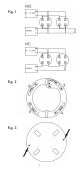
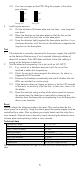
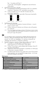
2.2. The detector needs four connections cables for installation.
Fig. 1 shows the wiring diagram, Fig. 2 the base plate.
The connection mark numbers are also shown inside the base
plate.
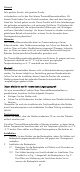
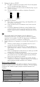
3. Setting the relay to NO/NC
3.1. The standard setting of the detector is NO. To change the
detector setting to NC, do the following.
3.2. Remove the two screws on the rear of the detector (Fig. 3) and
then remove the cover plate.