
User manual
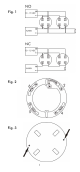
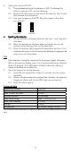

3. Setting the relay to NO/NC
3.1. The standard setting of the detector is NO. To change the
detector setting to NC, do the following.
3.2. Remove the two screws on the rear of the detector (Fig. 3) and
then remove the cover plate.
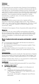
3.3. You see a jumper on the PCB. Plug the jumper in the other
pair of holes.
Setting NC Setting NO
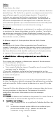
4. Installing the detector
4.1. On the outside of the base plate are two lines – one long and
one short.
4.2. Place the detector on the base plate so that the line on the
detector meets the short line on the base plate.
4.3. Press the detector lightly against the base plate and turn it in a
clockwise direction until the line on the detector is opposite the
long line on the base plate.
Test
1. If the detector is correctly connected to the power supply, the green
LED on the detector flashes every 3 to 5 seconds following a delay of
about 60 seconds. If the LED does not flash, either the cabling is
wrong or the detector is defective.
2. Use a test aerosol to test the detector.
2.1. Spray the test aerosol for at least 10 seconds into the smoke
chamber.
2.2. When sufficient aerosol has entered the chamber, the detector
triggers an alarm and the red LEDs light up continuously.
2.3. Reset the alarm system.
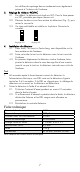
Technical data
Operating voltage 12 V DC
Closed-circuit current 320 µA
Max. current on alarm 35 mA
Startup duration 60 seconds
Max. relay rating Max. 1 A at 30 V DC
Max. wire diameter 2.5 mm
2
Weight 152 g
Dimensions Ø 98 mm, height 46 mm
The manufacturer reserves the right to make technical modifications at any
time.
5