
Manual


31
AZWG10000
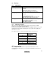
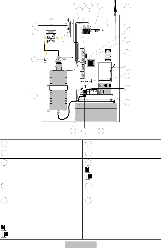
6. Components
BUS
+12 V
GND
LOCK
OPEN
RED
BLK
YEL
GRN
LD1 LD3 LD2
1
L. BAT
GS M
POWER
J14
1234 C
PLAY RE C
4
8
9
10
11
12
13
14
15
16
1718
19
20
3
765
NL
2
FUSE : T0.5A 250V
100-200V~50/60Hz
MAX:0.4A
J15
J13
COMINPUT TMP
N.C N. O
UØ1 UØ2 UØ3 UØ4 AUX
SETLINE
PHONE
1
Tamper contact (NC)
11
GSM module
2
Fuse (T 250 V/0.5 A)
12
Slot for SIM card
3
Grounding pin
13
J13: Jumper for tampering
= no tamper message
= tamper message (default)
4
Power supply unit (230V/14,5 V DC;
0,8 A)
14
Connecting clamps (see 9.2
Connections)
5
J14: Jumper for over-discharge
protection of battery. If the power from the
power supply unit fails, the device’s
standby battery is automatically
disconnected under a threshold of 10.5 V.
= No over-discharge protection
= over-discharge protection (default)
15
GSM antenna cable