Wireless 802.
FCC Certifications This equipment has been tested and found to comply with the limits for a Class B digital device, pursuant to Part 15 of the FCC Rules. These limits are designed to provide reasonable protection against harmful interference in a residential installation. This equipment generates, uses and can radiate radio frequency energy and, if not installed and used in accordance with the instructions, may cause harmful interference to radio communications.
Table of Content CHAPTER 1: INTRODUCTION ............................................................................................ 1 Features .............................................................................................................................. 1 Hardware Connection ....................................................................................................... 1 LED Indicators .................................................................................................
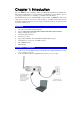
Chapter 1: Introduction This is an IEEE802.11b/g compliant 11 Mbps & 54 Mbps Ethernet Wireless Portable Router. The Wireless Portable Router is equipped with two 10/100 M Auto-sensing Ethernet ports for connecting to LAN and also for cascading to next Wireless Portable Router. This Portable Router provides 64/128bit WEP encryption, WPA and IEEE802.1x that ensures a high level of security to protects users’ data and privacy.
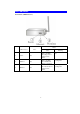
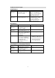
LED Indicators Front Panel: (LED Indicators) Status LED indicator 1 2 3 Power Ethernet Wireless Color Solid Turns solid Blue when the power is applied to this device. Blue Turns solid Blue when an Ethernet cable is connected. Turns solid Blue when the wireless is applied to this device.
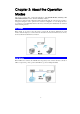
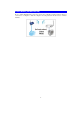
Chapter 2: About the Operation Modes This device provides three operational applications with Portable Router, Gateway, and Client (Infrastructure) modes, which are mutually exclusive. This device is shipped with configuration that is functional right out of the box. If you want to change the settings in order to perform more advanced configuration or even change the mode of operation, you can manually switch to the mode you desire by the manufacturer as described in the following sections.
Client Mode (Infrastructure) If set to Client (Infrastructure) mode, this device can work like a wireless station when it’s connected to a computer so that the computer can send packets from wired end to wireless interface.
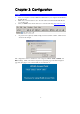
Chapter 3: Configuration Login 1. 2. 3. 4. Start your computer. Connect an Ethernet cable between your computer and the Wireless Portable Router. Make sure your wired station is set to the same subnet as the Wireless Portable Router, i.e. 192.168.1.254 Start your WEB browser. In the Address box, enter the following: http://192.168.1.254 No password is required by default, simply enter the username “admin”, which is fixed and cannot be changed.
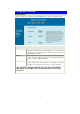
Common Connection Types Cable Modems Type Dynamic IP Address Details Your IP Address is allocated automatically, when you connect to you ISP. Static (Fixed) IP Address Your ISP allocates a permanent IP Address to you. ISP Data required Usually, none. However, some ISP's may require you to use a particular Hostname, Domain name, or MAC (physical) address. IP Address allocated to you. Some ISP's may also require you to use a particular Hostname, Domain name, or MAC (physical) address.
Configuration via Web Operation Mode Select an operation mode and then click the Setup button to enter its configuration page. Operation Mode Access Point Gateway Client When acting as an access point, this device connects all the stations (PC/notebook with wireless network adapter) to a wired network. All stations can have the Internet access if only the Access Point has the Internet connection. Select GW will enter the gateway mode.
AP Mode AP Mode Settings Alias Name Display the name of this device. Band You can choose one mode of the following you need. ~ 2.4GHz (B): 802.11b supported rate only. ~ 2.4GHz (G): 802.11g supported rate only. ~ 2.4GHz (B+G): 802.11b supported rate and 802.11g supported rate. The default is 2.4GHz (B+G) mode. The SSID differentiates one WLAN from another; therefore, all access points and all devices attempting to connect to a specific WLAN must use the same SSID.
Security Click the Setup button to enter the Wireless Security Setup page. Authentication: Select an authentication from the pull-down list including Open system or Shared Key, Open System, Open System with 802.1x, Shared Key, WPA-RADIUS, WPA-PSK, WPA2-RADIUS and WPA2PSK. Encryption: Select the type of encryption from the pull-down list either None or WEP. Apply Changes: Click this button to save and apply the current settings. Reset: Click to clear and reset the current settings.
of the requested transmission. If the “Hidden Node” problem is an issue, please specify the packet size. The RTS mechanism will be activated if the data size exceeds the value you set. The default value is 2346. Warning: Enabling RTS Threshold will cause redundant network overhead that could negatively affect the throughput performance instead of providing a remedy. The value can be set from 0 to 2346. This value should remain at its default setting of 2346.
Access Control WDS Setting Click the Setup button to enter the Wireless Access Control page. Wireless Access Control Mode: Select the Access Control Mode from the pull-down menu. • Disable: Select to disable Wireless Access Control Mode. • Allow Listed: Only the stations shown in the table can associate with the AP. • Deny Listed: Stations shown in the table won’t be able to associate with the AP. MAC Address: Enter the MAC address of a station that is allowed to access this Access Point.
MAC Address: Enter the AP MAC address in this column; the maximum input is 12 digits. Comment: Enter a comment or description for the AP MAC address. Apply Changes: Click to add a new MAC address. Reset: Click to clear previous settings. Current WDS List: This table displays you the AP MAC information. Delete Selected: To delete clients from access to this Access Point, you may firstly check the Select checkbox next to the MAC address and Comments, and press Delete Selected.
Channel Number Security device will not be permitted to join the BSS unless it can provide the unique SSID. A SSID is also referred to as a network name because essentially it is a name that identifies a wireless network. Allow user to set the channel manually or automatically. If set channel manually, just select the channel you want to specify.
Access Control that it is going to transmit the data. Upon receipt, the Access Point will respond with a CTS message to all station within its range to notify all other stations to defer transmission. It will also confirm the requestor station that the Access Point has reserved it for the time frame of the requested transmission. Beacon Interval: Enter a value between 20-1024 milliseconds. The Beacon Interval value indicates the frequency interval of the beacon.
WAN Port information. Delete Selected: To delete clients from access to this Router, you may firstly check the Select checkbox next to the MAC address and Comments, and press Delete Selected. Delete All: To delete all the clients from access to this Router, just press Delete All without selecting the checkbox. Reset: If you have made any selection, press Reset will clear all the select mark. Click Setup to enter the WAN Port Configuration screen.
Virtual Server DMZ Click Setup to enter the Virtual Servers screen. Enable Virtual Servers: Check to enable the virtual server function. Servers: Select the server type (Web, FTP, E-Mail (POP3), E-Mail (SMTP), DNS, Telnet) from the pull-down menu. Local IP Address: Enter the local server’s IP address. Protocol: Select the protocol (TCP, UDP or Both) used to the remote system or service. Port Range: For TCP and UDP Services, enter the beginning of the range of port numbers used by the service.
Reset: Click to resetore to the default values. Remote Management URL Filter Note: You need to give your LAN PC clients a fixed/static IP address for DMZ to work properly. Click Setup to enter the Remote Management screen. Enable Web Server Access via WAN: To permit remote access of the Router, from outside the local network, select to enable. Otherwise, keep the default setting, Disabled. Port Number: Enter the port number that will be open to outside access. Save: Click to save the current settings.
MAC Filter Click Setup to enter the MAC Filtering screen. IP Filter Enable MAC Filtering: Click to enable the MAC filtering function. MAC Address: For MAC filtering enters the 12-digit MAC address in the appropriate MAC field. Description: You may key in a description for the MAC address. Save: Click to save the current settings. Reset: Click to restore to the default values. Current Filter Table: Shows the current MAC address status.
DDNS Reset: Click to restore to the default values. Current Filter Table: Shows the current IP address status. Delete Selected: Select the unwanted IP addresses and then click the Delete Selected button to eliminate them. Delete All: Click to delete all the IP addresses in the table. Reset: Click to clear the current settings. Click Setup to enter the Dynamic DNS Setting screen. Dynamic DNS lets you update your current dynamic IP address with one or many dynamic DNS server so that anyone can contact you.
Client Mode Client Mode Settings Alias Name Display the name of this device. Band You can choose one mode of the following you need. ~ 2.4GHz (B): 802.11b supported rate only. ~ 2.4GHz (G): 802.11g supported rate only. ~ 2.4GHz (B+G): 802.11b supported rate and 802.11g supported rate. The default is 2.4GHz (B+G) mode. The SSID differentiates one WLAN from another; therefore, all access points and all devices attempting to connect to a specific WLAN must use the same SSID.
Advanced Settings Click Setup button to enter the Wireless Advanced Settings page. Fragment Threshold: Fragmentation mechanism is used for improving the efficiency when high traffic flows along in the wireless network. If your 802.11g Wireless LAN PC Card often transmit large files in wireless network, you can enter new Fragment Threshold value to split the packet. The value can be set from 256 to 2346. The default value is 2346.
Site Survey Apply Changes Reset environment to synchronize the transmitting timing including Synchronization and Start frame delimiter. If you want to change the Preamble type into Long or Short, please select the mode you need. Broadcast SSID: • Enabled: This wireless AP will broadcast its SSID to stations. • Disabled: This wireless AP will not broadcast its SSID to stations. If stations want to connect to this wireless AP, this AP’s SSID should be known in advance to make a connection.
Status System System Data System Firmware Version Firmware Date LAN Configuration MAC Address IP Address Network Mask Default Gateway DHCP Server DHCP Start IP Address DHCP Finish IP Address WLAN Configuration MAC Address SSID Channel Status Refresh The current version of the firmware installed in this device. The firmware released date. Shows the MAC address of this device. Shows the LAN IP address. Shows the LAN subnet mask. Shows the LAN default gateway. Shows the current DHCP Server status.
Active Clients Displays the Active Wireless Clients Table that is currently connecting with this Wireless Portable Router. Refresh Click to refresh the Active Wireless Client Table. TCP/IP LAN Interface Setup IP Address Default: 192.168.1.254 (this is the local address of this Router) Subnet Mask Default: 255.255.255.0 Default Gateway Shows the default gateway IP address.
DHCP Disable: Select to disable this Router to distribute IP Addresses (Disabled). Server: Select to enable this Router to distribute IP Addresses (DHCP Server). And the following field will be activated for you to enter the starting IP Address. DHCP Client Range The starting address of this local IP network address pool. The pool is a piece of continuous IP address segment. Keep the default value 192.168.1.1 should work for most cases. • Maximum: 253. Default value 253 should work for most cases.
Upgrade Firmware Browse Upload Reset Factory Default Click the Browse button, find and open the firmware file (the browser will display to correct file path). Click the Upload button to perform. Click the Reset button to restore default values. Click this button to come back to default factory settings. Reboot Click the Reboot button to restart the hardware system. Password Password Setup New Password Confirmed Password Apply Change Reset Maximum input is 36 alphanumeric characters (case sensitive).
Log Check the Enable Log box to show system log file. System Log System all Activates all logging functions. Wireless only Only logs related to the wireless LAN will be recorded. DDNS only Only logs related to DDNS will be recorded. WAN only Only logs related to WAN will be recorded. DHCP Server only Only logs related to DHCP Server will be recorded. Diagnostics Network Diagnostics - DNS Lookup Domain name /URL Enter Domain name /URL you would like to lookup, then click Start Lookup button.
Chapter 4: PC Configuration Overview For each PC, the following may need to be configured: • TCP/IP network settings • Internet Access configuration • Wireless configuration Windows Clients • This section describes how to configure Windows clients for Internet access via the Wireless Router. • The first step is to check the PC's TCP/IP settings.
Checking TCP/IP Settings - Windows 2000 1. 2. Select Control Panel - Network and Dial-up Connection. Right - click the Local Area Connection icon and select Properties. You should see a screen like the following: 3. 4. Select the TCP/IP protocol for your network card. Click on the Properties button. You should then see a screen like the following. 5. Ensure your TCP/IP settings are correct, as described below.
Using DHCP • To use DHCP, select the radio button Obtain an IP Address automatically. This is the default Windows setting. Using this is recommended. By default, the Wireless Router will act as a DHCP Server. • Restart your PC to ensure it obtains an IP Address from the Wireless Router. Using a fixed IP Address ("Use the following IP Address") If your PC is already configured, check with your network administrator before making the following changes.
4. Click on the Properties button. You should then see a screen like the following. 5. Ensure your TCP/IP settings are correct. Using DHCP • To use DHCP, select the radio button Obtain an IP Address automatically. This is the default Windows setting. Using this is recommended. By default, the Wireless Router will act as a DHCP Server. • Restart your PC to ensure it obtains an IP Address from the Wireless Router.
Internet Access To configure your PCs to use the Wireless Router for Internet access: • Ensure that the DSL modem, Cable modem, or other permanent connection is functional. • Use the following procedure to configure your Browser to access the Internet via the LAN, rather than by a Dial-up connection. For Windows 2000 1. 2. 3. 4. 5. 6. 7. Select Start Menu - Settings - Control Panel - Internet Options. Select the Connection tab, and click the Setup button.
Macintosh Clients From your Macintosh, you can access the Internet via the Wireless Router. The procedure is as follows. 1. Open the TCP/IP Control Panel. 2. Select Ethernet from the Connect via pop-up menu. 3. Select Using DHCP Server from the Configure pop-up menu. The DHCP Client ID field can be left blank. 4. Close the TCP/IP panel, saving your settings.
Wireless Station Configuration • This section applies to all Wireless stations wishing to use the Wireless Router's Access Point, regardless of the operating system that is used on the client. • To use the Wireless Portable Router in the Wireless Router, each Wireless Station must have compatible settings, as follows: The mode must be set to Infrastructure. Mode This must match the value used on the Wireless Router. The default SSID (ESSID) value is Untitled Note! The SSID is case sensitive.
Appendix A Troubleshooting A Overview This chapter covers some common problems that may be encountered while using the Wireless Router and some possible solutions to them. If you follow the suggested steps and the Wireless Router still does not function properly, contact your dealer for further advice. General Problems Problem 1: Solution 1: Can't connect to the Wireless Router to configure it.
Appendix A - Troubleshooting Wireless Access Problem 1: Solution 1: Problem 2: Solution 2: My PC can't locate the Wireless Portable Router. Check the following. • Your PC is set to Infrastructure Mode. (Access Points are always in Infrastructure Mode) • The SSID on your PC and the Wireless Portable Router are the same. Remember that the SSID is case-sensitive. So, for example "Workgroup" does NOT match "workgroup". • Both your PC and the Wireless Router must have the same setting for WEP.
Appendix B About Wireless LANs B BSS BSS A group of Wireless Stations and a single Access Point, all using the same ID (SSID), form a Basic Service Set (BSS). Using the same SSID is essential. Devices with different SSIDs are unable to communicate with each other. Channels The Wireless Channel sets the radio frequency used for communication. • Access Points use a fixed Channel. You can select the Channel used.
Appendix B - About Wireless LANs Regulatory Approvals CE Standards This product complies with the 99/5/EEC directives, including the following safety and EMC standards: • EN300328-2 • EN301489-1/-17 • EN60950 CE Marking Warning This is a Class B product. In a domestic environment this product may cause radio interference in which case the user may be required to take adequate measures.