MANUAL AND USER GUIDE Personal Alert System With DECT Technology www.ablenetinc.
PLEASE READ THIS MANUAL COMPLETELY AND SAVE IT FOR REFERENCE. Thank you for choosing Responsable by AbleNet – the most unique Personal Emergency Response System in the world, and covered by both US and Canadian patents. Responsable is your personal link to Family, Friends, or Emergency Personnel when needed. Responsable allows you to program up to 4 numbers to be reached at the push of a button.
Traveling? Whether you are moving across town or going to visit the grand kids across the country - just throw it in your suitcase. When you get to your destination, simply plug it into the local phone jack and power outlet. No additional programming is needed. And if you call 911, they will automatically have the local ‘caller ID’ of that location. Voice prompts provide easy set-up and testing.
Table Of Contents Limitation of Liability ................................................... 7 Installing the Batteries ................................................. 8 Pendant - small white batteries ...........................................8 Charging Extra Battery ........................................................9 Base - Larger AA Rechargeable Batteries ..............................9 Master ON/OFF switch ......................................................11 Connecting the Base Unit .....
Table Of Contents General Warnings and Precautions ............................. 42 Important Safety Instructions ...................................... 43 Manufacturer Disclaimers and Limited Warranty .......... 44 Limited Warranty .............................................................45 Return Material Authorization (RMA) .................................47 Replacement Parts / Optional Accessories .................. 48 Product Specifications ...............................................
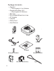
Package Contents • Pendant - 2 Rechargeable Li-Ion Batteries • Responsable Base Unit - 4 Rechargeable AA Batteries • • • • • • Belt Clip Wrist/Walker/Wheelchair strap AC Adapter Lanyard Phone Cord User Manual Pendant Base Unit AC Adapter W em st Sy y rt olog Ale hn al Tec on T rs EC Pe ith D M M AN M AN UAL L’U ANUE UAL Y AND TIL L E GU US ISA T G ÍA ER TEU UID DEL GUID R E D US E UAR E IO w.a ww Phone Cord ble tin ne om c.
Limitation of Liability This page is a summary of the Disclaimer and Limited Warranty disclosed in full at the end of this instruction manual. Read them. The purchaser agrees by using this product to the terms and conditions below and in the Disclaimer and Limited Warranty. The purchaser also agrees to read and follow all instructions and warnings on the product and contained within these Installation and Operation Instructions.
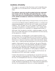
Installing the Batteries Pendant - small white batteries The Pendant requires one of the white/Li-Ion (Lithium Ion) batteries at any given time. The pendant should be able to run up to 4 months on a fully charged battery. The second battery is to be charging in the Base unit when not being used in the Pendant. There is no risk of over charging while in the base charger. Battery Cap To install the battery unscrew the battery cap of the Pendant. Install the battery with the negative side up facing the cap.
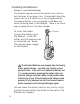
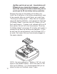
Charging Extra Battery Place the extra Pendant battery into the front charging area of the Base unit so that it will charge and be ready when its time to swap the batteries around. The LED on the right side will show red when charging and green when fully charged. LED NOTE: These white batteries are special batteries that are not available at your local store. See “Product Specifications” on page 49 for more details, or contact www.PrimaryVolt.com to purchase replacement batteries.
When you first get your unit - these batteries will probably be low, or even fully discharged - and will need to be charged for 24 hours before being able to provide you the 24 hour battery back-up protection. Remove the cover on the bottom of the Base unit. Install the 4 batteries in the battery compartment area. A few seconds after you install these, you might hear “Running on battery power”.
Master ON/OFF switch The System has a Master ON/OFF switch on the bottom of the base unit – just left of the rechargeable batteries. This switch controls all power: back up batteries and power from the AC adapter. This switch should be ON at all times while the unit is in use. This switch should only be turned OFF if the unit is taken out of service.
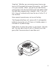
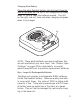
Connecting the Base Unit Power Connection Simply plug in the AC Adapter in to the nearest electrical outlet. Plug the other end of the AC power adapter into the Base unit. You need to push the plug into the opening in the Base unit and twist 90’ clockwise to lock in place. To remove in the future, simply rotate 90’ counter-clockwise and pull outward. rn Lea t de se Co Re V 7.
wall, and the other end into either one of the telephone jacks at the back of the Base unit. Note - you will feel a ‘click’ when the cords are firmly seated in the receptacles. Use with existing phones It is recommended that you plug a conventional telephone into the open jack on the Base Unit. This will allow the phone to be used by other members of your household and is an important step when programming emergency contact numbers.
How to Handle VoIP and DSL If Your Phone System is VoIP Voice-over-Internet Protocol (VoIP) is a telephone service that sends your call over the Internet instead of through the regular telephone system. The System will work with most VoIP systems. It is important (if you haven’t already done so) that you register your physical address with your VoIP provider and check to ensure that 911 service is available to you.
How to Handle DSL If your home has DSL service for your computer, you must use a DSL filter in line with the System or it will not work. This filter can be obtained from a local electronics supplier or your DSL service provider. See illustration below. DSL Filter rn Lea t de se Co Re DC ne ho p Tele Jack V 7.
Base Unit Options and Features The System can work right out of the box with no programming. To avoid programming any telephone numbers, simply slide the slide switch at the back of the Base unit to the “911 Only” mode. Then, when you push the blue button on the Pendant - you will be immediately connected to 911 emergency services.
How does the Base unit know when to go to the next number? The base unit will first dial the first number in the “Friends” list. About 10 seconds into the conversation, the Base unit will interrupt the call and announce “This is an emergency call. If you want to continue this call - Press 5 now. Otherwise, we will hang up and call the next contact or emergency operator”. At this point - the person that is being called must press the “5” key on their telephone if they want to continue the call.
Programming the Base Unit Programming Telephone Numbers If you choose to only contact 911 - and not a custom telephone number - skip these next steps (and go to page 16) - and make sure your slide switch on the back of the Base unit is set to “911 only”. Programming Notes • As you program the system using your telephone, you will hear the base unit speak each number as it is pushed. • Dial slowly and listen for each number to be announced. If you did not hear the announcement - the number was not recorded.
Step 1: Write out the numbers - use the worksheet on page 21. Below we will refer to Number 1 as the first number, Number 2 as the second number etc. Include area-codes and a 1 or 9 if they are needed for dialing. Step 2: Using the conventional telephone plugged into the Base Unit, (page 12) establish a live phone connection with a friend or family member. A personal mobile phone in the same house is recommended.
Note: Once you exit Programming Mode, adding additional numbers requires starting over and re-entering ALL Emergency Contact numbers. You cannot simply add a new number to the end of the sequence or change Emergency Contact number 2, for example. Step 7: When you have completed entering all Emergency Contact numbers, the Base Unit will speak, “End of programming”. Move the slider switch back to Friends & 911, Friends Only, or 911 Only to exit Programming Mode.
Programming Worksheet 1. Call a friend or family member on your telephone. 2. Slide switch to LEARN MODE [voice prompt – Learn Mode] 3. Enter: “1 2 3 4 #” [voice prompt – one, two, three, four, “#” Enter 1st phone number followed by # ] 4. (Enter the 1st phone number then “#”) : __ __ __ __ __ __ __ __ __ __ __ __ __ __ __ __ # [voice prompt – numbers as you enter them then “Enter 2nd phone number followed by #] Press # again to skip remaining numbers, or 5.
Programming Special Features There are a few features you can program into the System. A typical user will not need these features - and may skip to the next page. If you choose to change any of these features, use the same programming set-up as before: 1. First establish a phone connection with another phone such as your cell phone. 2.
is used to DEMO the unit without having access to a telephone line. We use this feature with a Viking DLE200 test box. NEVER LEAVE THE UNIT IN THIS MODE FOR NORMAL OPERATION. 1. Enter 1234** [Voice prompt – Option Mode] 2. Enter – 4 [Voice prompt – DEMO Tradeshow Mode], 1 for YES 3 for NO– FACTORY SETTING 3. Enter either 1 or 3 [Voice prompt 1 – YES] [Voice prompt 3 – NO] 4. Enter “#” (to exit programming mode) [Voice prompt – Programming complete] 5.
4. Enter # (to exit programming mode) [Voice prompt – Programming complete] 5. Slide Programming Switch to “Friend, 911 – Friends Only – 911 Only” Option #9 – Reset To Factory Settings (This option will ERASE all programmed friend numbers and reset all options.) 1. Enter 1234** [Voice prompt – Option Mode] 2. Enter – 9 [Voice prompt – Reset to factory settings, 1 for YES – 3 for NO 3. Enter either 1 or 3 [Voice prompt 1 – YES] or [Voice prompt 2 – NO] 4.
Adding Additional Pendants to the System The System comes with one Pendant. If you want to add additional pendants to your system - follow the directions here. The Pendant’s unique ID code should already be paired with the Base unit when it came from the factory. You can add a total of 4 Pendants and Emergency Wall Communicators (see “Replacement Parts / Optional Accessories” on page 48) to the system by pairing each pendant’s ID code with the Base unit.
3. When Pendant learning has been successful you will hear “All Systems are OK” and then it will announce the call setting that the base is set to – Friends 911 Mode, Friends Only or 911 Only. • If “Base and Pendant out of Range” or “Pendant Learning Failed” is heard from the Base or Pendant, STOP - wait 30 seconds and start at step #1 again. Notes: • You have up to 45 seconds after pushing the RED Code Learn button on the base unit to get the pendant to enter “Pendant Learning” Mode.
Operating the System Emergency Dialing Using the Pendant In the event of an emergency, press the Blue button on the front of the Pendant. When this button is pressed for 2 seconds, the System will automatically start dialing from the list of numbers. Blue Button If set to the “911 only” mode, then the 911 emergency operator will be called. When the emergency response operator answers, speak in a normal voice and you will be heard.
Holding the Pendant Hold the Pendant as you would any normal telephone receiver - close to the head so that you can hear the other person being called - and they can hear you speaking. Hanging -Up If you choose to cancel the call once initiated - you can simply push the Gray button on the back for a second to cancel the call and you will hear “Hanging up”. The recipient can force a hang up by pushing “9”, or simply hang up their end. The System will hang-up automatically over the next 1 to 3 minutes.
Answering an Incoming Call with the Pendant The System has the ability to answer incoming calls through the pendant or the Emergency Wall Communicator accessory. When the phone rings (the pendant will NOT ring), push the Blue Emergency button or Red “HELP” button on the Emergency Wall Communicator for 2 seconds to answer the call. Red “Help” Button Blue Button t Tes Pendant Optional Emergency Wall Communicator accessory Example: 1. Incoming call to customers home 2. Base unit rings 3.
Lanyard, Belt Clip or Wrist Strap. The System includes 3 accessories for carrying/wearing the Pendant: a lanyard, belt clip, and wrist-strap. The wrist-strap can also be used to attach the Pendant to a wheelchair, bed rail or other object as-needed.
Battery Check To check the status of the Pendants battery, Press and Release the Gray button at the back of the Pendant. A voice announcement will announce one of the following messages: Battery is ok-Check the battery condition twice a month. Battery is low-The battery should be replaced within the next week. Replace battery now-The battery should be replaced immediately. To replace the battery - simply exchange the battery in the Pendant with the battery that has been charging in the Base unit.
The battery should be tested at least twice a month along with the System Check outlined on the next page. When it gets to the point after a few years that the pendant battery only lasts 4 weeks before needing to be charged - it is then time to replace both the Pendant batteries. Note: This is a very unusual battery not available at most outlets. Order replacement batteries from www.PrimaryVolt.com as directed on”Replacement Parts / Optional Accessories” on page 48.
System Check The Gray button on the back of the pendant will also perform a SYSTEM CHECK. Press and hold this button for more than four (4) seconds. One of the following announcements will be made. “All systems are ok.” This confirms the following: - Battery status. - The Pendant is working. - The Base unit is working. - The Base unit is connected to a working phone line. - The Pendant is within range of the Base unit. “System cannot detect dial tone.
If you receive a failure notification, please refer to the “Troubleshooting Guide” on page 37 of this manual to determine the cause. This testing feature is very useful - allowing you to confirm that the system has coverage from all parts of your home. Simply walk to the various parts of your home and push the Battery Check / System Check button until you hear the 4 beeps and then the dial tone.
Operating Range The operating range of your System will depend on many factors including intervening walls, electrical interference or various appliances such as vacuum cleaners, microwave ovens, mixers, coffee grinders, hair dryers and other sources of electrical noise around the house. The system should cover your typical home and a short distance into your yard. Perform the System Check on page 20 to determine the boundaries of your system to know the limits of operation in your home and surroundings.
Periodic Testing / Maintenance It is highly recommended that you preform a full System Check (see page 33) at least twice a month. This will confirm that the Pendant battery is in good condition and that the Base unit is able to get a dial tone. Replacing Batteries Replace the Base unit batteries every 2 years - or as needed. Be sure to purchase NiMH AA batteries with 2400 mAh or greater capacity.
Troubleshooting Guide What if I can’t get the System to work? Step 1 – Check the PENDANT. What to do: Press the Gray Battery Test / System Check button on the back of the Pendant. What to expect: A voice should announce the condition of the battery. A light on the front of the Pendant will come on. If nothing happens, the most likely cause is that the battery is dead or has been installed backwards. If the Pendant says “Battery ok”, go on to step 3.
Step 3 – Make sure the Pendant and the Base unit are communicating with each other. Background information: The Pendant and the Base unit are connected by a wireless radio link. They must be synchronized to work together. They should have already been synchronized at the factory, but resetting this is simple.
Information The FCC Wants You To Know FCC ID: TYD3X911 This device complies with Part 15 of the FCC Rules. Operation is subject to the following two conditions: (1) this device may not cause harmful interference, and (2) this device must accept any interference received, including interference that may cause undesired operation. Privacy of communications may not be ensured when using this product.
This equipment also complies with Part 68 of the FCC rules and the requirements adopted by the ACTA: US:TYDW400B3X911 REN: 0.0B a) On the bottom of this equipment is a label that contains, among other information, a product identifier - in this case, US:TYDW400B3X911. If requested, this number must be provided to the telephone company. b) An applicable certification jacks Universal Service Order Codes (USOC) for the equipment is provided (i.e.
f) The telephone company may make changes in its facilities, equipment, operations or procedures that could affect the operation of the equipment. If this happens the telephone company will provide advance notice in order for you to make necessary modifications to maintain uninterrupted service. g) Should you experience trouble with this equipment, please contact AbleNet at 800-322-0956 for repair or warranty information.
General Warnings and Precautions Warning! • Manufacturer DOES NOT represent this unit to be waterproof. To reduce the risk of damage to the unit, DO NOT expose the pendant or base unit to prolonged water, rain or moisture. • The System is intended for residential use only. It may not work properly if connected to some commercial phone systems. • The System works with tone dialing systems only. Do not use if you have pulse dialing only.
Important Safety Instructions When using your System , please observe the following instructions in order to reduce the risk of personal injury, electrical shock, or fire. 1. Save these instructions for future reference. 2. Read all instructions carefully and make sure you understand them. 3. Unplug this product from the electrical outlet before attempting to clean it. Do not use any liquids for cleaning either the Base unit or the Pendent. Use only a soft damp cloth. 4.
Manufacturer Disclaimers and Limited Warranty COMMUNICATION AND RESPONSE LIMITATIONS: Purchaser acknowledges that signals which are transmitted over telephone lines, or other modes of communication pass through communication networks wholly beyond the control of Manufacturer and are not maintained by Manufacturer, and, therefore, Manufacturer shall not be responsible for any equipment or communication failure which prevents transmission signals from reaching your contact list including emergency 911 operato
TESTING AND SERVICE OF Responsable EQUIPMENT: The equipment, once installed, are in the exclusive possession and control of the Purchaser, and it is Purchaser’s sole responsibility to test the operation of equipment and request warranty service if the equipment is under warranty. Limited Warranty AbleNet Manufactured Products include a ‘Two Year Limited Warranty’. This warranty is against defects in materials and manufacturing for two full years from the date of purchase.
THE FOLLOWING ARE EXCLUDED FROM THE ABOVE LIMITED WARRANTY COVERAGE: • Wear and Tear. Periodic maintenance, repair, and replacement of parts due to normal wear and tear are excluded from coverage. • Abuse. Defects or damage that result from: (a) improper operation, storage, misuse or abuse, accident or neglect, such as physical damage (cracks, scratches, etc.
ON THE LENGTH OF AN IMPLIED WARRANTY, SO THE ABOVE LIMITATIONS OR EXCLUSIONS MAY NOT APPLY TO YOU. THIS WARRANTY GIVES YOU SPECIFIC LEGAL RIGHTS, AND YOU MAY ALSO HAVE OTHER RIGHTS THAT VARY FROM STATE TO STATE OR FROM ONE JURISDICTION TO ANOTHER. Return Material Authorization (RMA) No Product may be returned directly to AbleNet without first contacting AbleNet at 1(800)322-0956 or via the website at www.ablenetinc.com, for a Return Material Authorization (“RMA”) number.
Replacement Parts / Optional Accessories Rechargeable Li-Ion Batteries www.primaryvolt.com Rechargeable AA Batteries www.primaryvolt.com t Tes Pendant PN: 80001900 Emergency Wall Communicator PN: 80001800 This wall button can be permanently mounted to the bedroom or bathroom wall - and provide the same 2-way voice communication, just like the Pendant in an emergency. Visit AbleNet’s website at www.ablenetinc.com or call 1-800-322-0956 for more product information and pricing.
Product Specifications RF Technology: 1.9 Ghz DECT System Operating Range Covers your typical American house and into the front, back, and side yards. Power Adapter Ratings Input: 110 VAC Output: 7.5 volts DC - 500 mA Base Unit Power Consumption 120 mA in standby mode 200 mA when dialing Back-up Battery Supply AA NiMH 2400 mAh batteries (4 pieces). Should be replaced every 2 years. (Note that lower or larger capacity batteries can be used - they will just give less or more back-up supply time).
AbleNet, Inc. Mpls./Saint Paul, MN 55113 800-322-0956 www.ablenetinc.com www.ablenetinc.