
User`s manual
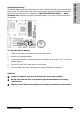

Hardware Setup
AN-M2/AN-M2HD 1-15
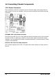
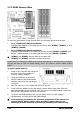
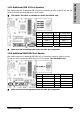
1.8.3 Additional USB 2.0 Port Headers
Each header supports 2x additional USB 2.0 ports by connecting bracket or cable to the rear I/O
panel or the front-mounted USB ports of your chassis.
※ The header “FP-USB4” is available for model “AN-M2HD” only.
Pin Pin Assignment Pin Pin Assignment
1 VCC 2 VCC
3 Data0 - 4 Data1 -
5 Data0 + 6 Data1 +
7 Ground 8 Ground
10 NC
※ Make sure the connecting cable bears the same pin assignment.
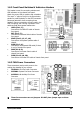
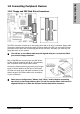
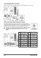
1.8.4 Additional IEEE1394 Port Header
Each header supports 1x additional IEEE1394 port by connecting bracket or cable to the rear
I/O panel or the front-mounted IEEE1394 port of your chassis.
(For AN-M2HD only)
Pin Pin Assignment Pin Pin Assignment
1 TPA0 + 2 TPA0 -
3 Ground 4 Ground
5 TPB0 + 6 TPB0 -
7 +12V 8 +12V
10 Ground
※ Make sure the connecting cable bears the same pin assignment.