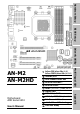
Hardware Setup BIOS Setup Driver & Utility 2000MT/s HT Dual Channel DDR2 800 NVIDIA PureVideo™ NVIDIA nView™ HDMI (AN-M2HD) / DVI (AN-M2) Multilingual QIG AN-M2 AN-M2HD GeForce 7025/nForce 630a (AN-M2) GeForce 7050PV/nForce 630a (AN-M2HD) Gigabit LAN Motherboard AMD Socket AM2 USB 2.0 / IEEE1394 (AN-M2HD) User’s Manual Vista HW Ready 7.
AN-M2/AN-M2HD User’s Manual English + Multilingual QIG P/N: 4310-0000-84 Rev. 3.00, April 2007 Copyright and Warranty Notice The information in this document is subject to change without notice and does not represent a commitment on part of the vendor, who assumes no liability or responsibility for any errors that may appear in this manual. No warranty or representation, either expressed or implied, is made with respect to the quality, accuracy or fitness for any particular part of this document.
Hardware Setup Contents 1. Hardware Setup ............................................................... 1-1 BIOS Setup 1.1 Specifications............................................................................... 1-1 1.1.1 AN-M2 ................................................................................ 1-1 1.1.2 AN-M2HD............................................................................ 1-2 1.2 Motherboard Layout .....................................................................
3. Driver & Utility ................................................................. 3-1 3.1 3.2 3.3 3.4 3.5 3.6 3.7 3.8 3.9 CD-ROM AUTORUN ...................................................................... 3-1 nVidia nForce Chipset Driver ......................................................... 3-2 Realtek HD Audio Driver ............................................................... 3-2 Cool’n’Quiet Driver ....................................................................... 3-4 USB 2.0 Driver .
Hardware Setup 1. Hardware Setup 1.1 Specifications 1.1.
1.1.
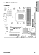
Hardware Setup 1.2 Motherboard Layout 1.2.
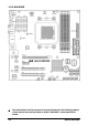
1.2.2 AN-M2HD ※ 1-4 The motherboard and its component layouts illustrated in the following chapter of this manual were mainly based on model “AN-M2HD”, unless specifically stated.
• Choose a chassis big enough to install this motherboard. • As some features for this motherboard are implemented by cabling connectors on the motherboard to indicators and switches or buttons on the chassis, make sure your chassis supports all the features required. • If there is a possibility of adopting some more hard drives, make sure your chassis has sufficient power and space for them. • Most chassis have alternatives for I/O shield located at the rear panel.
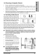
1.5 Checking Jumper Settings • • For a 2-pin jumper, plug the jumper cap on both pins will make it CLOSE (SHORT). Remove the jumper cap, or plug it on either pin (reserved for future use) will leave it at OPEN position. SHORT OPEN OPEN Pin 1~2 SHORT Pin 2~3 SHORT For 3-pin jumper, pin 1~2 or pin 2~3 can be shorted by plugging the jumper cap in. 1.5.
An onboard battery saves the CMOS memory to keep the BIOS information stays on even after disconnected your system with power source. Nevertheless, this backup battery exhausts after some five years. Once the error message like “CMOS BATTERY HAS FAILED” or “CMOS checksum error” displays on monitor, this backup battery is no longer functional and has to be renewed. To renew the backup battery: 1. Power off the system and disconnect with AC power source. 2. Remove the exhausted battery. 3.
1.6 Connecting Chassis Components 1.6.1 Power Connectors These connectors provide the connection from an ATX power supply. As the plugs from the power supply fit in only one orientation, find the correct one and push firmly down into these connectors. ATXPWR1: ATX 24-Pin Power Connector The power supply with 20-pin or 24-pin cables can both be connected to this 24-pin connector. Connect from pin-1 for either type.
Hardware Setup 1.6.2 Front Panel Switches & Indicators Headers This header is used for connecting switches and LED indicators on the chassis front panel. Watch the power LED pin position and orientation. The mark “+” align to the pin in the figure below stands for positive polarity for the LED connection. Please pay attention when connecting these headers. A wrong orientation will only result in the LED not lighting, but a wrong connection of the switches could cause system malfunction.
1.7 Installing Hardware ※ DO NOT scratch the motherboard when installing hardware. An accidentally scratch of a tiny surface-mount component may seriously damage the motherboard. 1.7.1 CPU Socket AM2 ※ DO NOT touch or bend the delicate pins on the CPU whenever you are holding it. The installation procedures vary with different types of CPU fan-and-heatsink assembly. The one shown here is served for DEMO only.
Hardware Setup 4. Place the heatsink and fan assembly onto the retention frame. Match the heatsink clip with the socket mounting-lug. Hook the spring clip to the mounting-lug. 5. On the other side, push the retention clip straight down to lock into the plastic lug on the retention frame. 6. Connect the CPU cooling fan power cable to the CPUFAN1 connector on this motherboard. ※ The “CPUFAN1” connector can be connected either with a 3-Pin or 4-Pin CPU cooling fan.
1.7.2 DDR2 Memory Slots To reach the performance of Dual Channel DDR2, the following rules must be obeyed: • For a 2-DIMM dual-channel installation: Populate DIMM modules of the same type and size on slots [DIMM1]+[DIMM2], or slots [DIMM3]+[DIMM4]. • For a 4-DIMM dual-channel installation: Populate 2 DIMM modules of the same type and size on slots [DIMM1]+[DIMM2], and another 2 DIMM modules of the same type and size on slots [DIMM3]+[DIMM4]. ※ [DIMM1] and [DIMM2] slots are made of the same color.
Hardware Setup 1.8 Connecting Peripheral Devices 1.8.1 Floppy and IDE Disk Drive Connectors The FDC1 connector connects up to two floppy drives with a 34-wire, 2-connector floppy cable. Connect the single end at the longer length of ribbon cable to the FDC1 on the board, the two connectors on the other end to the floppy disk drives connector. Generally you need only one floppy disk drive in your system.
1.8.2 Serial ATA Connectors Each SATA connector serves as one single channel to connect one SATA device by SATA cable. To connect SATA device: 1. Attach either end of the signal cable to the SATA connector on motherboard. Attach the other end to the SATA device. 2. Attach the SATA power cable to the SATA device and connect the other end from the power supply. ※ The motherboard in this photo is served for DEMO only, and may not be the same type or model as the one described in this user’s manual.
Each header supports 2x additional USB 2.0 ports by connecting bracket or cable to the rear I/O panel or the front-mounted USB ports of your chassis. ※ ※ The header “FP-USB4” is available for model “AN-M2HD” only. Pin Pin Assignment Pin 1 VCC 2 Pin Assignment VCC 3 Data0 - 4 Data1 - 5 Data0 + 6 Data1 + 7 Ground 8 Ground 10 NC Make sure the connecting cable bears the same pin assignment. 1.8.
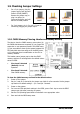
1.8.5 Internal Audio Connectors This connector connects to the audio output of internal CD-ROM drive or add-on card. 1.8.6 Front Panel Audio Connection Header This header provides the front panel connection for HD (High Definition) Audio, yet for AC’97 Audio CODEC connection, you must carefully check the pin assignment before connecting from the front panel module. An incorrect connection may cause malfunction or even damage the motherboard.
The audio driver is originally configured to support HD Audio. For AC’97 audio connection, you may: 1. Right-click the “Realtek HD Audio Manager” icon in system tray. 2. Click “Audio I/O” tab, and then click “Connector Settings”. 3. Click “Disabled front panel jack detection”, and then click “OK” to confirm.
1.8.7 S/PDIF Output Connection Header This header provides the S/PDIF output connection to your add-on HDMI VGA card. (For AN-M2HD only) Pin Pin Assignment 1 VCC (5V) 2 x 3 S/PDIF Out 4 Ground 1.8.8 PCI and PCI Express X16, X1 Slots Install PCI Express X16 graphics card into slot “PCIEXP1”. Install PCI Express X1 cards into slot “PCIE1”. Install PCI cards into slots “PCI1”, and/or “PCI2”.
Hardware Setup 1.9 Onboard Indicators 1.9.1 Power Source Indicators • 5VSB: This LED lights up when the power supply is connected with power source. • VCC: This LED lights up when the system power is on.
1.10 Connecting Rear Panel I/O Devices The rear I/O part of this motherboard provides the following I/O ports: AN-M2 AN-M2HD • Mouse: Connects to PS/2 mouse. • Keyboard: Connects to PS/2 keyboard. • OPT-OUT1: This connector provides an S/PDIF-Out connection through optical fiber to digital multimedia devices. • HDMI1: Connects to multimedia devices of HDMI protocol.
2. BIOS Setup This motherboard provides a programmable EEPROM so that you can update the BIOS utility. The BIOS (Basic Input/Output System) is a program that deals with the basic level of communication between processor and peripherals. Use the BIOS Setup program only when installing motherboard, reconfiguring system, or prompted to “Run Setup”. This chapter explains the Setup Utility of BIOS utility.
2.1 SoftMenu Setup This option configures the CPU’s clock and voltage. Phoenix – AwardBIOS CMOS Setup Utility SoftMenu Setup AMD Athlon(tm) 64 X2 Dual Core Processor 4800+ Frequency : 2400MHz CPU Operating Speed x - CPU External Clock(MHz) x - PCIe Clock x - Multiplier Factor Default 200MHz 100MHz x12 Voltages Control x - CPU Core Voltage x - DDR2 Voltage Default 1.300 V 1.
- Multiplier Factor This item displays the multiplier factor for the CPU you installed. Voltages Control This option allows you to switch between the default and user-defined voltages. Leave this setting at default unless the current voltage setting cannot be detected or is not correct. The option “User Define” enables you to select the following voltages manually.
2.2 Standard CMOS Features Date (mm:dd:yy) Time (hh:mm:ss) ► ► ► ► ► ► Phoenix – AwardBIOS CMOS Setup Utility Standard CMOS Features Wed, Apr 12 2007 12 : 34 : 56 IDE Channel 1 Master IDE Channel 1 Slave SATA Channel 1 SATA Channel 2 SATA Channel 3 SATA Channel 4 None None None None None None Drive A Drive B Floppy 3 Mode Support Halt On 1.44M, 3.5 in.
IDE HDD Auto-Detection This item allows you to detect the parameters of IDE drives by pressing key. The parameters will be shown on the screen automatically. IDE Channel 1 Master/Slave, SATA Channel 1~4 When set to [Auto], the BIOS will automatically check what kind of IDE or SATA hard drive you are using. If you want to define your own drive yourself, set it to [Manual] and make sure you fully understand the meaning of the parameters.
[All, But Keyboard]: The system-boot will stop for all errors except a keyboard error. [All, But Diskette]: The system-boot will stop for all errors except a diskette error. [All, But Disk/Key]: The system-boot will stop for all errors except a diskette or keyboard error. Base Memory This item displays the amount of base memory installed in the system. The value of the base memory is typically 640K for systems with 640K or more memory size installed on the motherboard.
2.3 Advanced BIOS Features Item Help :Move Enter:Select +/-/PU/PD:Value F10:Save ESC:Exit F1:General Help F5: Previous Values F6: Fail-Safe Defaults F7: Optimized Defaults Quick Power On Self Test When set to [Enabled], this item speeds up the Power On Self Test (POST) after powering on the system. The BIOS shorten or skip some check during the POST. Hard Disk Boot Priority This item selects the hard disks booting priority.
[System]: The password is required each time the computer boots up. ※ Don’t forget your password. If you forget the password, you will have to open the computer case and clear all information in the CMOS before you can start up the system. But by doing this, you will have to reset all previously set options. MPS Version Ctrl For OS This item specifies which version of MPS (Multi-Processor Specification) this motherboard will use. Leave this item at its default setting.
2.4 Advanced Chipset Features Phoenix – AwardBIOS CMOS Setup Utility Advanced Chipset Features K8<->NB HT Speed Auto K8<->NB HT Width Auto ► DRAM Configuration Press Enter SSE/SSE2 Instructions Enabled iGPU Frame Buffer Control Auto x - VGA Share Memory 64M Item Help K8<->NB HT Speed This item selects the LDT Bus Frequency between CPU and Chipset. K8<->NB HT Width This item selects the LDT Bus Width between CPU and Chipset. DRAM Configuration Click key to enter its submenu.
2.5 Integrated Peripherals Phoenix – AwardBIOS CMOS Setup Utility Integrated Peripherals ► OnChip IDE/SATA Device Press Enter Init Display First PCIe OnChip USB V1.1+V2.
IDE/SATA Function Setup Click key to enter its submenu: Phoenix – AwardBIOS CMOS Setup Utility IDE/SATA Function Setup IDE 1 Controller Enabled IDE DMA Transfer Access Enabled OnChip SATA Controller Enabled Item Help BIOS Setup :Move Enter:Select +/-/PU/PD:Value F10:Save ESC:Exit F1:General Help F5: Previous Values F6: Fail-Safe Defaults F7: Optimized Defaults IDE 1 Controller This item allows you to enable or disable the IDE1 controller.
OnChip SATA Mode This item determines the mode for OnChip SATA. [IDE]: The on-chip SATA served as IDE mode. [RAID]: The on-chip SATA served as RAID mode. - SATA1 RAID ~ SATA4 RAID This item allows you to enable or disable the RAID function for each of the SATA1 ~ SATA4 port individually. Back to Integrated Peripherals Setup Menu Init Display First This item allows you to choose the primary display card. OnChip USB This option enables or disables the USB controller.
2.6 Power Management Setup Item Help :Move Enter:Select +/-/PU/PD:Value F10:Save ESC:Exit F1:General Help F5: Previous Values F6: Fail-Safe Defaults F7: Optimized Defaults ACPI Suspend Type This item selects the type of Suspend mode. - USB Resume from S3 When set to [Enabled], this item allows you to use a USB device to wake up a system that is in the S3 (STR - Suspend To RAM) state. This item can be configured only if the item “ACPI Suspend Type” is set to [S3(STR)].
Wake Up by Alarm When set to [Enabled], you can set the date and time you would like the Soft-Off PC to power-on in the “Date (of Month) Alarm” and “Time (hh:mm:ss) Alarm” items. However, if the system is being accessed by incoming calls or the network (Resume On Ring/LAN) prior to the date and time set in these items, the system will give priority to the incoming calls or network instead.
2.7 PnP/PCI Configurations Phoenix – AwardBIOS CMOS Setup Utility PnP/PCI Configurations Resources Controlled By Auto(ESCD) x IRQ Resources Press Enter PCI/VGA Pallete Snoop Item Help Disbaled ** PCI Express relative items ** Maximum Payload Size 4096 Resources Controlled By This item configures all of the boot and Plug-and-Play compatible devices. [Auto(ESCD)]: The system will automatically detect the settings. [Manual]: Choose the specific IRQ resources in the “IRQ Resources” menu.
2.8 PC Health Status Phoenix – AwardBIOS CMOS Setup Utility PC Health Status Item Help CPU Shutdown Temperature 90°C/194°F CPU Warning Temperature 80°C/176°F FAN Fail Alarm Selectable Disabled Shutdown When FAN Fail Disabled CPU FanEQ Control Enabled - CPU FanEQ Target Temp. 50°C/122°F - CPU FanEQ Temp. Tolerance 5°C/ 41°F - CPU FanEQ Start Control 80% - CPU FanEQ Stop Control 50% SYS FanEQ Control Enabled - SYS FanEQ Reference Temp. System - SYS FanEQ Target Temp. 35°C/ 95°F - SYS FanEQ Temp.
- CPU FanEQ Temp. Tolerance This item sets the temperature tolerance range for the item “CPU FanEQ Target Temp.”. - CPU FanEQ Start Control This item sets the speed ratio for the 4-pin CPU fan assembly connected at “CPUFAN1” fan power connector to start running. - CPU FanEQ Stop Control This item sets the lowest speed ratio for the 4-pin CPU fan assembly connected at “CPUFAN1” fan power connector to run at when the CPU temperature detected is lower than the value of item “CPU FanEQ Target Temp.
All Voltages, Fans Speed and Thermal Monitoring These unchangeable items list the current status of the CPU and environment temperatures, fan speeds, and system power voltage. 2.9 Load Fail-Safe Defaults This option loads the BIOS default values for the most stable, minimal-performance system operations. 2.10 Load Optimized Defaults This option loads the BIOS default values that are factory settings for optimal-performance system operations. 2.
3. Driver & Utility The “Driver-&-Utility CD” that came packed with this motherboard contains drivers, utilities and software applications required for its basic and advanced features. 3.1 CD-ROM AUTORUN To run the CD-ROM automatically: 1. Place the “Driver-&-Utility CD” into the CD-ROM drive in your system. The following installation auto-run screen appears. If not, browse the root directory of the CD-ROM via the File Manager, and double click the “AUTORUN” file. 2.
3.2 nVidia nForce Chipset Driver To install this program: 1. Click on the [Drivers] tab in the installation menu screen. 2. Click the [nVidia nForce Chipset Driver] item. The installation screen appears. 3. Follow the prompts on the screen to complete installation. ※ Please install this nVidia nForce Chipset Driver first after having installed the Windows operating system. 3.3 Realtek HD Audio Driver To install this program: 1. Click on the [Drivers] tab in the installation menu screen. 2.
5. Click the [Audio I/O] tab. 6. Click the pull down menu to select the channel configuration. 7. Click [OK] button to apply the Audio I/O settings and exit.
3.4 Cool’n’Quiet Driver To install this program: 1. Click on the [Drivers] tab in the installation menu screen. 2. Click the [Cool’n’Quiet Driver] item. The installation screen appears. 3. Follow the prompts on the screen to complete installation. 4. Restart the system for the driver to take effect. 5. After the system restarted, open the “Power Options” from the control panel and choose the power scheme “Minimal Power Management” to enable Cool ‘n’ Quiet.
3.6 abitEQ (The Hardware Doctor Utility) The abitEQ is a self-diagnostic system that protects PC Hardware by monitoring critical items of Power Supply Voltage, CPU & System Fans Speed, and CPU & System Temperature. To install this utility: Click on the [abit Utility] tab in the installation menu screen. 2. Click the [abitEQ] item. The following screen appears. 3. Follow the prompts on the screen to complete installation. 4.
3.7 FlashMenu (BIOS Update Utility) The FlashMenu is a utility to flash the BIOS in a more easily and quickly way. To install this utility: 1. Click on the [abit Utility] tab in the installation menu screen. 2. Click the [FlashMenu] item. The following screen appears. 3. Follow the prompts on the screen to complete installation. 4. Execute the FlashMenu by entering the Windows Menu [Start] [All Programs] [abit] [FlashMenu] [FlashMenu]. 5. This FlashMenu screen appears.
3.8 SATA RAID Driver (for Windows Vista) The Raid Driver needed when installing Windows Vista operating system is located at the following path of your CD-ROM drive after placing the “Driver-&-Utility CD” into it: For Vista 32bit CD-ROM Drive:\Drivers\SATARAID\MCP68\Vista32 For Vista 64bit CD-ROM Drive:\Drivers\SATARAID\MCP68\Vista64 3.
3-8 AN-M2/AN-M2HD
4. Multilingual Quick Installation Guide 4.1 Français//Guide d'Installation Rapide Ce “Guide d’Installation rapide ” contient seulement l information de base dont vous pouvez avoir besoin lors de l’installation de votre carte mère abit. Pour des opérations plus avancées, vous devez vous reporter à la version complète. • [SPKR]: Connecte au câble du Haut-parleur du système. • [SLED]: Connecte au câble de la DEL de veille.
4.2 Deutsch//Kurze Installationsanleitung Diese “Kurze Installationsanleitung” enthält nur die grundlegenden Hardwareinformationen, die Sie zur Installation Ihres abit-Motherboards benötigen. Details finden Sie im ausführlichen Handbuch. Vorsichtsmaßnahmen beim Einrichten der Hardware • Vor Installation des Motherboards und Ändern von Einstellungen müssen Sie immer die Stromversorgung ausschalten und den Stecker von der Steckdose abziehen.
4.3 Italiano//Guida all’installazione rapida Questa “Guida all’installazione rapida” contiene solamente le informazioni di base sull’hardware necessarie all’installazione della scheda madre abit. Fare riferimento alla versione completa della guida per eseguire le operazioni avanzate. Precauzioni sull’installazione dell’hardware • Spegnere sempre l’unità e scollegare il cavo d’alimentazione dalla presa CA prima di installare la scheda o modificare qualsiasi impostazione.
4.4 Español//Guía rápida de instalación Esta “Guía de instalación rápida” contiene solamente la información básica sobre el hardware que puede necesitar durante la instalación de la placa base abit. Para conocer el funcionamiento avanzado, es necesario consultar la versión completa. Precauciones durante la configuración del hardware • Apague siempre la fuente de alimentación y desenchufe el cable antes de instalar la placa base o cambiar su configuración.
4.5 Português//Guia de instalação rápida Este “Guia de instalação rápida” contém apenas informação essencial sobre o hardware e necessária à instalação da sua placa principal abit. Para mais informações, terá de consultar a versão integral deste guia. Normas de segurança a ter em conta durante a montagem do hardware • Desligue sempre a fonte de alimentação e desligue o cabo de alimentação da tomada a.c. antes de instalar a placa ou alterar quaisquer definições.
4.6 Русский//Краткое руководство по установке В “Кратком руководстве по установке” содержится только основная информация о техническом обеспечении, которая вам может понадобиться при установке материнской платы abit. Описание дополнительных операций вы найдете в полной версии руководства. Предостережения по установке технического обеспечения • Перед тем, как установить плату или поменять установку, обязательно выключите питание и выдерните шнур питания из розетки.
4.7 Eesti//Kiirpaigaldusjuhend Käesolev “Kiirpaigaldusjuhend” sisaldab ainult abit-emaplaadi paigaldamiseks vajalikku riistvaraalast põhiteavet. Edasijõudnud kasutamiseks tuleb teil ikkagi pöörduda täisversiooni poole.
4.8 Latviski//Ātrās instalēšanas instrukcija Šī “Ātrās instalēšanas instrukcija” ietver tikai pamata norādes iekārtai, kas nepieciešamas, instalējot abit mātesplati. Pilnīgākai darbībai nepieciešams iegūt instrukcijas paplašināto variantu. Piesardzības pasākumi iekārtas uzstādīšanā • Vienmēr pirms plates pievienošanas vai jebkuru uzstādījumu izmaiņām izslēdziet strāvas padevi un atvienojiet vadu no maiņstrāvas barošanas avota.
4.9 Lietuvių//Trumpas instaliavimo vadovas Šiame “Trumpame instaliavimo vadove” pateikta tik esminė informacija apie techninę įrangą, kurios jums gali prireikti instaliuojant pagrindinę plokštę abit. Papildomų operacijų aprašymą rasite pilnoje vadovo versijoje.
4.10 Polski//Instrukcja szybkiej instalacji Ta “Instrukcja szybkiej instalacji” zawiera tylko podstawowe informacje dotyczące sprzętu, wymagane podczas instalacji płyty głównej abit. Przy zaawansowanych operacjach, niezbędne będzie skorzystanie z kompletnej wersji instrukcji. Środki bezpieczeństwa przy instalacji sprzętu • Przed instalacją płyty lub zmianą jakichkolwiek ustawień, należy zawsze wyłączyć zasilanie i odłączyć przewód zasilający od źródła zasilania prądem zmiennym.
4.11 Magyar//Gyorstelepítési útmutató Ez a “Gyorstelepítési útmutató” csak azt az alapvető hardver információt tartalmazza, amely az abit alaplap telepítéséhez szükséges. Az előrehaladott üzemeltetéshez, továbbra is a teljes útmutatót kell használnia. Hardver beállítási óvintézkedések • Minding kapcsolják ki a tápot ás áramtalanítsák a készüléket az alaplap telepítése vagy a beállítások módosítása előtt.
4.12 Türkçe//Hızlı Kurulum Kılavuzu Bu “Hızlı Kurulum Kılavuzu”, abit anakartınızı takmanızda gerekebilecek sadece temel donanım bilgisini içermektedir. İleri işlemler için daha geniş olan tam versiyonuna başvurmanız gerekecektir. Donanım Kurmada Alınacak Önlemler • Anakartı takmadan veya ayarları değiştirmeden önce daima • • • • güç beslemeyi kapatarak güç kablosunu elektrik prizinden çekin.
Multilingual QIG اﻟﻠﻐﺔ اﻟﻌﺮﺑﻴﺔ//دﻟﻴﻞ اﻟﺘﺮآﻴﺐ اﻟﺴﺮﻳﻊ 4.
ﻓﺎرﺳﯽ //راهﻨﻤﺎﯼ ﻧﺼﺐ ﺳﺮﻳﻊ AN-M2/AN-M2HD 4.
4.
4.16 한국어//빠른 설치 가이드 [SPKR]: 시스템 스피커 케이블에 연결하세요. [SLED]: 유휴(Suspend) LED 케이블에 연결하세요. [PWR]: 전원 스위치 케이블에 연결하세요. [PLED]: 전원 LED 케이블에 연결하세요. 본 “빠른 설치 가이드”는 빅빔 abit 메인보드 설치에 필요한 중요한 하드웨어 정보만을 포함하고 있습니다. 보다 상세한 정보 및 과정은 사용자 설명서를 참고하시기 바랍니다. • • • • 하드웨어 설치시 주의사항 추가 USB 포트 헤더: [FP-USB1], [FP-USB2] • 메인보드 설치 또는 설정을 변경하시기 전에는 추가 IEEE1394 포트 헤더: [FP-1394-1], [FP-1394-2] 항상 전 원을 끄고, AC 콘센트를 제거하시기 바랍니다. • 정전기 방지 비닐에서 메인보드를 빼 낼때는 정전기 안전 손목 접지대를 착용하고 메인보드의 가장 자리를 잡으시기 바랍니다.
4.17 Bahasa Malaysia//Panduan Pemasangan Ringkas “Panduan Pemasangan Ringkas” ini hanya mengandungi maklumat perkakasan asas yang anda mungkin perlu semasa memasang papan induk abit anda. Untuk pengendalian lanjutan, anda perlu rujuk ke versi lengkapnya. • • • • • Langkah Berjaga-jaga bagi Penyediaan Perkakasan • Sentiasa matikan bekalan kuasa dan keluarkan kord kuasa dari alur keluar AU sebelum memasang papan atau menukarkan apa-apa pengesetan.
4.
4.19 繁體中文 4.19.1 規格:AN-M2 處理器 • 支援採用 Hyper Transport™技術、 2000MT/s 系統匯流排的 AMD Socket AM2 940 處理器 • 支援 AMD CPU Cool ‘n’ Quiet 技術 晶片組 • NVIDIA GeForce 7025 / nForce 630a 記憶體 • 4 條 240 針腳 DIMM 插槽支援最大 8GB 記憶體容量 • 支援雙通道 DDR2 800 無緩衝 ECC/非 ECC 記憶體 圖形埠 • 整合 GeForce7 系列顯示晶片 • 支援 DirectX 9.0、Shader Model 3.0 以及 nView • 可程式設定 PureVideo HD 影像處理器 擴充插槽 • 1 個 PCI-E X16 插槽 • 1 個 PCI-E X1 插槽 • 2 個 PCI 插槽 內部輸入/輸出接頭 • 1 個軟碟埠 • 1 個 Ultra ATA 133 IDE 接頭 • 4 個 SATA 3Gb/s 接頭 • 3 個 USB 2.
4.19.2 規格:AN-M2HD 處理器 • 支援採用 Hyper Transport™技術、 2000MT/s 系統匯流排的 AMD Socket AM2 940 處理器 • 支援 AMD CPU Cool ‘n’ Quiet 技術 晶片組 • NVIDIA GeForce 7050PV / nForce 630a 記憶體 • 4 條 240 針腳 DIMM 插槽支援最大 8GB 記憶體容量 • 支援雙通道 DDR2 800 無緩衝 ECC/非 ECC 記憶體 圖形埠 • 整合 GeForce7 系列顯示晶片 • 支援 DirectX 9.0、Shader Model 3.0 以及 nView • 可程式設定 PureVideo HD 影像處理器 HDMI • 內建 HDMI 端子支援聲音/影像輸出 擴充插槽 • 1 個 PCI-E X16 插槽 • 1 個 PCI-E X1 插槽 • 2 個 PCI 插槽 內部輸入/輸出接頭 • 1 個軟碟埠 • 1 個 Ultra ATA 133 IDE 接頭 • 4 個 SATA 3Gb/s 接頭 • 4 個 USB 2.
4.19.
4.20 简体中文 4.20.1 规格:AN-M2 处理器 • 支持采用 Hyper Transport™(超传输)技 术、2000MT/s 系统总线的 AMD Socket AM2 940 处理器 • 支持 AMD CPU Cool ‘n’ Quiet(降温静音) 技术 芯片组 • NVIDIA GeForce 7025 / nForce 630a 内存 • 4 条 240 针脚 DIMM 插槽支持最大 8GB 内存容量 • 支持双信道 DDR2 800 无缓冲 ECC/非 ECC 内存 图形端口 • 整合 GeForce7 系列显示芯片 扩充插槽 • 1 个 PCI-E X16 插槽 • 1 个 PCI-E X1 插槽 • 2 个 PCI 插槽 内部输入/输出接头 • 1 个软盘端口 • 1 个 Ultra ATA 133 IDE 接头 • 4 个 SATA 3Gb/s 接头 • 3 个 USB 2.
4.20.2 规格:AN-M2HD 处理器 • 支持采用 Hyper Transport™(超传输)技 术、2000MT/s 系统总线的 AMD Socket AM2 940 处理器 • 支持 AMD CPU Cool ‘n’ Quiet(降温静音) 技术 芯片组 • NVIDIA GeForce 7050PV / nForce 630a 内存 • 4 条 240 针脚 DIMM 插槽支持最大 8GB 内存容量 • 支持双信道 DDR2 800 无缓冲 ECC/非 ECC 内存 图形端口 • 整合 GeForce7 系列显示芯片 • 支持 DirectX 9.0、Shader Model 3.0 以及 nView • 可程序设定 PureVideo HD 影像处理器 HDMI • 内建 HDMI 端子支持声音/影像输出 扩充插槽 • 1 个 PCI-E X16 插槽 • 1 个 PCI-E X1 插槽 • 2 个 PCI 插槽 内部输入/输出接头 • 1 个软盘端口 • 1 个 Ultra ATA 133 IDE 接头 • 4 个 SATA 3Gb/s 接头 • 4 个 USB 2.
4.20.
5. Appendix 5.1 Troubleshooting (How to Get Technical Support?) 5.1.1 Q & A Q: Do I need to clear the CMOS before I use a new motherboard to assemble my new computer system? A: Yes, we highly recommend that you clear the CMOS before installing a new motherboard. Please move the CMOS jumper from its default 1-2 position to 2-3 for a few seconds, and then back. When you boot up your system for the first time, follow the instructions in the user's manual to load the optimized defaults.
Q: How to get a quick response for my request on technical support? A: Please carry out a simple troubleshooting before sending “Technical Support Form”: System boot-up fails after the system had been assembled: Check the motherboard’s supporting specifications first to see if all the key components attached in your system can meet. To do so, you may: • Remove all the unnecessary add-on devices (except the CPU, VGA card, DRAM, and Power Supply), and then reboot.
• Memory configuration: Type in the memory configuration in BIOS setting. Example: Memory Timing: 2.5-3-3-7 @533MHz • Graphics information: Note Graphics card’s brand, model and driver version • Graphics card: Type in the brand and model name of your graphics card. Example: ATI RADEON X850 XT PE • Graphics driver version: Type in the driver version of your graphics card Example: Catalyst 5.12V • Power supply maker: Type in the brand and model name of your power supply unit.
5.1.
5.1.3 Contact Information Taiwan Head Office Universal ABIT Co., Ltd. 6F, No. 323, Yang Guang St., Neihu, Taipei, 114, Taiwan Tel: 886-2-8751-3380 Fax: 886-2-8751-3381 Sales: sales@abit.com.tw Austria, Czech, Romania, Bulgaria, Slovakia, Croatia, Bosnia, Serbia, Macedonia, Slovenia Universal ABIT Austria Computer GmbH Schmalbachstrasse 5, A-2201 Gerasdorf / Wien, Austria Marketing: market@abit.com.tw Tel: 43-1-7346709 Fax: 43-1-7346713 North America, South America Contact: office@abit-austria.
http://www.abit.com.tw P/N: 4310-0000-84 Rev. 3.