
Cut Sheet


2CDC002177D0203 - 5
Miniature Circuit Breaker SU200 M
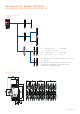
Influence of adjacent devices
If several miniature circuit breakers are installed directly side
by side with high load on all poles, a correction factor has to
be applied to the rated current (see table). If distance pieces
are used, the factor is not to be considered.
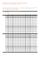
C, K characteristics Z characteristics
Rated current Internal resistance
per pole
Power loss Internal resistance
per pole
Power loss
I
n
R
i
P
v
R
i
P
v
A mΩ W mΩ W
0.2 42500 1.7 - -
0.3 18889 1.7 - -
0.5 5600 1.4 9000 2.3
0.75 2489 1.4 - -
1 1400 1.4 2200 2.2
1.6 703 1.8 1000 2.6
2 450 1.8 650 2.6
3 178 1.6 250 2.3
4 113 1.8 140 2.2
5 50 1.3 100 2.5
6 56 2.0 70 2.5
8 23 1.5 28 1.8
10 21 2.1 21 2.1
13 14 2.3 17 2.9
15 11 2.4 13 2.9
16 9.8 2.5 10 2.6
20 6.3 2.5 6.5 2.6
25 5.1 3.2 5.1 3.2
30 3.9 3.5 3.9 3.5
32 3.6 3.7 3.6 3.7
35 3.3 4.1 3.3 4.1
40 2.8 4.5 2.8 4.5
50 1.8 4.5 1.8 4.5
60 1.4 4.9 1.4 4.9
63 1.4 5.4 1.4 5.4
Internal resistances are subject to application-specific and environment-specific conditions
and are therefore to be considered as typical values.
Internal resistance and power loss per pole
Influence of adjacent devices, internal resistance and
power loss
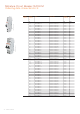
Miniature Circuit Breaker SU200 M Derating
No. of adjacent devices Factor F
1 1
2, 3 0.9
4, 5 0.8
≥ 6 0.75