
Cut Sheet


2 - 2CDC002177D0203
Miniature Circuit Breaker SU200 M
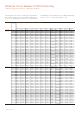
General Data
Standards UL 489, CSA 22.2 No. 5, IEC/EN 60947-2
Poles 1P, 2P, 3P, 4P
Tripping characteristics C, K, Z
Rated current I
n
0.2 - 63 A
Rated frequency f 50 / 60 Hz, DC (0 Hz)
Rated insulation voltage U
i
acc. to IEC/EN 60664-1 250 V AC (phase to ground), 440 V AC (phase to phase)
Overvoltage category III
Pollution degree 3
IEC/EN 60947-2
Rated operational voltage U
e
1P: 230 V AC; 2P, 3P, 4P: 400 V AC
Max. power frequency recovery voltage U
max
AC 1P: 253 V AC; 2P, 3P, 4P: 440 V AC
Min. operating voltage 12 V AC, 12 V DC
Rated ultimate short-circuit breaking capacity I
cu
15 kA
Rated service short-circuit breaking capacity I
cs
≤ 40 A: 11.25 kA
> 40 A: 7.5 kA
Rated impulse withstand voltage U
imp
(1.2/50µs) 4 kV (test voltage 6.2 kV at sea level, 5 kV at 2,000 m)
Dielectric test voltage 2 kV (50 / 60Hz, 1 min.)
Reference temperature for tripping characteristics 30 °C
Electrical endurance I
n
< 30 A: 20,000 ops (AC), I
n
≥ 30 A: 10,000 ops. (AC);
1 cycle (2 s - ON, 13 s - OFF, I
n
≤ 32 A), 1 cycle (2 s - ON, 28 s - OFF, I
n
> 32 A)
UL / CSA
Rated voltage AC
AC
AC
AC
DC
1P: 277 V AC up to 40 A for C, Z char.,
277 V AC up to 35 A for K char., 240 V AC
2P, 3P, 4P: 480 Y / 277 V AC up to 40 A for C, Z char.,
480 Y / 277 V AC up to 35 A for K char., 240 V AC
1P: 48 V DC; 2P: 96 V DC (2p in series)
Rated interrupting capacity acc. to UL 1077 –
Short-circuit current rating acc. to UL 489 10 kA
Application –
Reference temperature for tripping characteristics 40 °C
Electrical endurance 6,000 ops (AC), 6,000 ops. (DC); 1 cycle (1 s - ON, 9 s - OFF)
Mechanical data
Housing Insulation group II, RAL 7035
Toggle Insulation group II, black, sealable
Contact position indication Real CPI (green OFF / red ON)
Protection degree acc. to DIN EN 60529 IP20*, IP40 in enclosure with cover
Mechanical endurance 20,000 ops.
Shock resistance acc. to IEC/EN 60068-2-27 25 g - 2 shocks - 13 ms
Vibration resistance acc. to IEC/EN 60068-2-6 5g - 20 cycles at 5…150…5 Hz with load 0.8 I
n
Environmental conditions (damp heat cyclic) acc. to IEC/EN 60068-2-30 28 cycles with 55°C/90-96% and 25°C/95-100%
Ambient temperature -25 … +55°C
Storage temperature -40 ... +70 °C
Installation
Terminal Failsafe bi-directional cylinder-lift terminal
Cross-section of conductors (top/bottom) solid, stranded: 35 mm² / 35 mm²
flexible: 25 mm
2
/ 25 mm
2
18 – 4 AWG
Cross-section of busbars (top/bottom) 10 mm² / 10 mm²
18 – 8 AWG
Torque 2.8 Nm
AWG 18-16: 13.3 in-lbs.
AWG 14-10: 17.7 in-lbs.
AWG 8-4: 39.8 in-lbs.
Screwdriver No. 2 Pozidrive
Mounting On DIN rail 35 mm acc. to EN 60715 by fast clip
Mounting position any
Supply optional
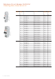
Dimensions and weight
Mounting dimensions acc. to DIN 43880 Mounting dimension 3
Pole dimensions (H x D x W) 111 x 69 x 17.5 mm
Pole weight approx. 125 g
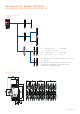
Combination with auxiliary elements
Auxiliary contact Yes
Signal contact Yes
Shunt trip Yes
Technical data
*
Also fulfilling the requirements acc. to the protection degree IPXXB