
Datasheet


US Catalog | Miniature Circuit Breakers 41
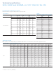
Voltage between conductors
U
n
500 VDC
all-pole disconnection
500 VDC
1-pole disconnection
500 VDC
all-pole disconnection
Voltage between conductor and
ground U
n
250 VDC–
circuit symmetrically grounded
250 VDC–
unsymmetrically grounded
250 VDC– circuit ungrounded or
unsymmetrically grounded
MCB 2-pole
S202MUC
2-pole
S202MUC
4-pole
S204MUC
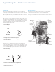
Supply from below
1 in the circuit diagram, the negative pole is earthed. 2 in the circuit diagram, the positive pole is earthed.
SK 0115 Z 94 SK 0114 Z 94
SK 0196 Z 98
Voltage between conductors U
n
250 VDC 500 VDC 500 VDC 500 VDC 500 VDC
Voltage between conductor and
ground U
n
250 VDC 250 VDC 500 VDC 250 VDC 250 VDC
MCB 1-pole
S201MUC
2-pole
S202MUC
2-pole
S202MUC
2-pole
S202MUC
4-pole
S204MUC
Supply from below
Supply from above
1 in the circuit diagram, the negative pole is earthed. 2 in the circuit diagram, the positive pole is earthed.
Examples of permissible voltages between the conductors depending on the number of poles and circuit layout:
Examples of permissible voltages between the conductors depending on the number of poles and circuit layout:
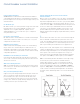
Miniature circuit breaker S200MUC
Use of MCBs in direct current circuits
S200MUC miniature circuit breakers can be used in the 1 pole
version at 250 VDC, and in the 2-pole or 4-pole version with
series connection of two poles up to 500 VDC.
S200MUC differs from the standard S200 type. It is equipped with
permanent magnets that assist in the forced extinguishing of the arc.
If voltages to ground exceeding 250 VDC occur, 2-pole S200MUC
should be used for one-pole disconnection and four-pole S200MUC
for all-pole disconnection.
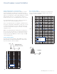
For DC incoming supply from above
S200MUC MCBs have permanent magnets in the area of arc
chutes. Therefore, it is necessary to take into account the polarity
during the installation process. In the case of a short circuit, the
magnetic field of the permanent magnets corresponds with the
electromagnetic field of the short-circuit current, therefore, safely
leading the short circuit into the arc chute. Incorrect polarities
may cause damage to the MCB. As a result for top-fed devices,
terminal 1 must be connected to (-) and terminal 3 to (+).