
Installation manual


221
Sungrow
Sungrow
Solar-Log™ terminal strip connector RJ45 socket inverter
Terminal PIN
► 1 ► 3 (Data+ A)
► 4 ► 6 (Data- B)
2. Insert the plug into the socket on the inverter
3. If only one inverter is to be connected, terminate this in accordance with the inverter instructions
between round socket Pin 2 and 3 with 120Ω.
4. Insert the terminal block connector into the Solar-Log™ RS485 socket.
Connect the inverters to each other
•
Wiring with a self-made RS485 cable,
•
RJ45 socket and COM round sockets on the outside of the inverter,
Procedure
Connect a cable between the RJ45 and round sockets.
•
Connect the first inverter as explained above.
•
Connect the second inverter via the RS485/WiFi socket.
•
Connect wires as shown in the diagram below.
Round socket RS485/WiFi
Inverter 1
RJ45 socket
Inverter 2
Terminal PIN
► 3 (B RS485) ► 3 (Data+ B)
► 2 (A RS485) ► 6 (Data- A)
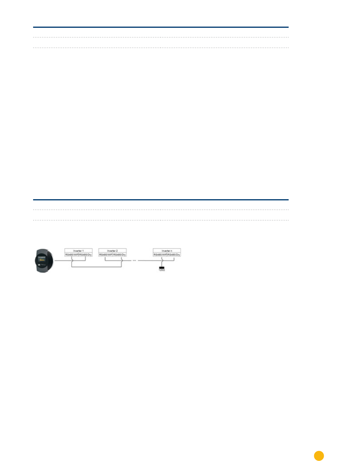
Figure 11: Sungrow wiring diagram with several inverters
•
Connect the other inverters to each other in the same way.
•
Terminate the last inverter between round socket Pin 2 and 3 with 120 Ω.
•
Insert the terminal block connector into the Solar-Log™ RS485 socket.
Allocate communication address
•
Recommendation: Continuous numbering starting with 1.
•
Setting: Using the inverter operating display
•
Procedure: Start according to the inverter's instructions