
Installation manual


200
Solar Max
SolarMax – Cx series
68�2 SolarMax – Cx series
Easy Installation Termination Addressing Sensors RS485 Meters RS485 Interface
Yes
No
Yes
Yes Yes RS485
Overview
•
Interface not integrated; Retrofit RS485 interface card.
•
6-pin wiring
•
Communication address must be allocated.
•
Installation steps
• Switch off the inverters and Solar-Log™
• Install the RS485 interface in the inverter
• Connect inverters to the Solar-Log™
• Connect the inverters to each other
• Allocate communication address
Installing the RS485 interface
Procedure
► Install the RS485 interface in the inverter in accordance with the interface card installation in-
structions.
Connect inverters to the Solar-Log™
The wiring is done using a
•
ready-made data cable (optional extra; not supplied)
or
•
self-made cable connection using RS485 data cable with RJ45 plug and terminal block connector
Caution
Risk of damage to the unit!
The Solar-Log™ also has an RJ45 socket, which must never be connected to the RJ45
socket on the inverter.
► OnlyconnectinvertersviatheRS485/422Solar-Log™interface(s).
Procedure
1. Open the inverter as shown in the inverter's instructions.
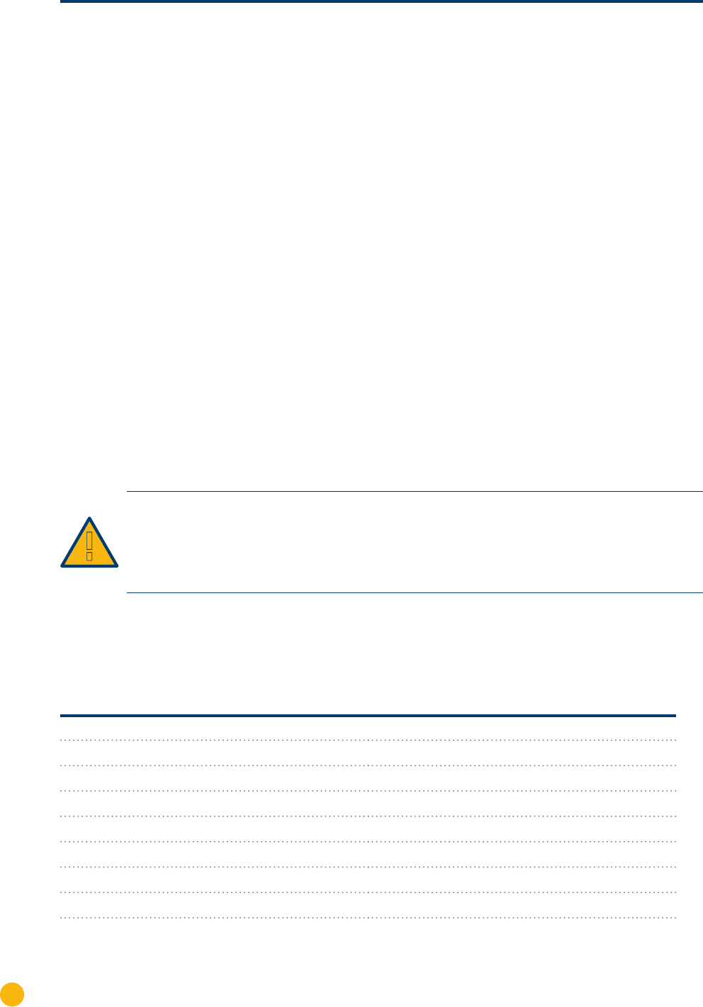
2. If you are making the cable yourself, connect the wires as shown in the following diagram:
Solar-Log™ terminal strip connector RJ45 inverter
Terminal PIN
► 1 ► 7
► 2 ► 1
► 2 ► 2
► 3 ► 3
► 3 ► 4
5 - unused
6 - unused
► 4 ► 8
3. Insert the RJ45 plug into any RJ45 socket on inverter 1.
4. Close the inverter if no other inverters are to be connected.