
Installation Manual

Description
12
RFID
1
G
*
*
3G/4G
* *
*
*
*
*
*
*
*
3
H
*
L
*
3
IN
J
K
M
4 4 4 4 4
1
2
O
4
OUT
N
4
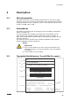
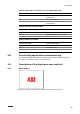
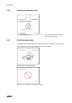
A
Serial number
E
Barcode with the part number of the
EVSE
B
Part number of the EVSE
F
Power rating of the EVSE
C
Product model number
G
Ambient temperature
D
Barcode with the serial number of the
EVSE
H
Mass of the EVSE
Note: The data in the illustration is only an example. Find the
type plate on your EVSE to see the applicable data. Refer to
section 2.6.2.
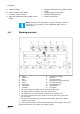
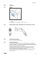
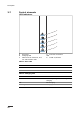
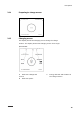
2.4
Working principle
A LEDs
B Ethernet
C WiFi
D 3G/4G
E RFID
F Bluetooth
G CPU system
H Isolation
I AC/DC power supply
J AC input
K
Surge protection
L
Earth(ground) fault protection
M AC input metering
N AC isolation relay
O Control pilot
P AC output
1. The user initiates a charge session request (black lines).
2. The EVSE verifies the status of the EV (purple lines).
3. The EVSE goes on and AC power goes to the EV (yellow lines).
4. The charge session starts. AC power flows from the power grid to the
EV (red lines).
5. The electrical interfaces of the EVSE communicate with the on-board
computer (blue lines).
(*): Connections between parts of the EVSE and the CPU system. The arrow
shows the direction of the input and output signals.
A
B
C
D
E
F
I
P