
Data Sheet
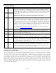
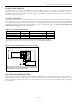
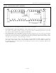
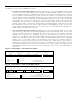
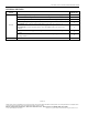
Table Of Contents
- TYPICAL OPERATING CIRCUIT
- PIN CONFIGURATIONS
- ORDERING INFORMATION
- ABSOLUTE MAXIMUM RATINGS
- RECOMMENDED DC OPERATING CONDITIONS
- (TA = 0 C to +70 C, TA = -40 C to +85 C.) (Notes 1, 2)
- DC ELECTRICAL CHARACTERISTICS
- (VCC = 4.5V to 5.5V; TA = 0 C to +70 C, TA = -40 C to +85 C.) (Notes 1, 2)
- DC ELECTRICAL CHARACTERISTICS
- (VCC = 0V, VBAT = 3.0V; TA = 0 C to +70 C, TA = -40 C to +85 C.) (Notes 1, 2)
- AC ELECTRICAL CHARACTERISTICS
- (VCC = 4.5V to 5.5V; TA = 0 C to +70 C, TA = -40 C to +85 C.)
- CAPACITANCE
- (TA = +25 C)
- 64 x 8, Serial, I2C Real-Time Clock
- SYMBOL
- TIMING DIAGRAM
- RS1

DS1307 64 x 8, Serial, I
2
C Real-Time Clock
REVISION HISTORY
REVISION
DATE
DESCRIPTION
PAGES
CHANGED
100208
Moved the Typical Operating Circuit and Pin Configurations to first page.
1
Removed the leaded part numbers from the Ordering Information table.
1
Added an open-drain transistor to SQW/OUT in the block diagram (Figure 1).
4
Added the pullup voltage range for SDA, SCL, and SQW/OUT to the Pin
Description table and noted that SQW/OUT can be left open if not used.
6
Added default time and date values on first application of power to the Clock
and Calendar section and deleted the note that initial power-on state is not
defined.
8
Added default on initial application of power to bit info in the Control Register
section.
9
Updated the Package Information section to reflect new package outline
drawing numbers.
13
3/15
Updated Benefits and Features section
1
14 of 14
Maxim cannot assume responsibility for use of any circuitry other than circuitry entirely embodied in a Maxim product. No circuit patent licenses are implied. Maxim
reserves the right to change the circuitry and specifications without notice at any time.
Maxim Integrated Products, 120 San Gabriel Drive, Sunnyvale, CA 94086 408-737-7600
© 2015 Maxim Integrated Products Maxim is a registered trademark of Maxim Integrated Products, Inc.