
Data Sheet

© 2006 Microchip Technology Inc. DS21034D-page 3
MCP3202
Sample Capacitor C
SAMPLE
— 20 — pF See Figure 4-1
Digital Input/Output:
Data Coding Format Straight Binary
High Level Input Voltage V
IH
0.7 V
DD
—— V
Low Level Input Voltage V
IL
——0.3 V
DD
V
High Level Output Voltage V
OH
4.1 — — V I
OH
= -1 mA, V
DD
= 4.5V
Low Level Output Voltage V
OL
——0.4 VI
OL
= 1 mA, V
DD
= 4.5V
Input Leakage Current I
LI
-10 — 10 µA V
IN
= V
SS
or V
DD
Output Leakage Current I
LO
-10 — 10 µA V
OUT
= V
SS
or V
DD
Pin Capacitance
(All Inputs/Outputs)
C
IN
, C
OUT
— — 10 pF V
DD
= 5.0V (Note 1)
T
AMB
= 25°C, f = 1 MHz
Timing Parameters:
Clock Frequency f
CLK
——1.8
0.9
MHz
MHz
V
DD
= 5V (Note 2)
V
DD
= 2.7V (Note 2)
Clock High Time t
HI
250 — — ns
Clock Low Time t
LO
250 — — ns
CS Fall To First Rising CLK
Edge
t
SUCS
100 — — ns
Data Input Setup Time t
SU
— — 50 ns
Data Input Hold Time t
HD
— — 50 ns
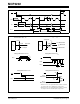
CLK Fall To Output Data Valid t
DO
— — 200 ns See Test Circuits, Figure 1-2
CLK Fall To Output Enable t
EN
— — 200 ns See Test Circuits, Figure 1-2
CS
Rise To Output Disable t
DIS
— — 100 ns See Test Circuits, Figure 1-2
Note 1
CS
Disable Time t
CSH
500 — — ns
D
OUT
Rise Time t
R
— — 100 ns See Test Circuits, Figure 1-2
Note 1
D
OUT
Fall Time t
F
— — 100 ns See Test Circuits, Figure 1-2
Note 1
Power Requirements:
Operating Voltage V
DD
2.7 — 5.5 V
Operating Current I
DD
— 375 550 µA V
DD
= 5.0V, D
OUT
unloaded
Standby Current I
DDS
—0.5 5 µACS = V
DD
= 5.0V
Temperature Ranges:
Specified Temperature Range T
A
-40 — +85 °C
Operating Temperature Range T
A
-40 — +85 °C
Storage Temperature Range T
A
-65 — +150 °C
Thermal Package Resistance:
Thermal Resistance, 8L-PDIP
θ
JA
—85—°C/W
Thermal Resistance, 8L-SOIC θ
JA
— 163 — °C/W
Thermal Resistance, 8L-MSOP
θ
JA
— 206 — °C/W
Thermal Resistance, 8L-TSSOP
θ
JA
——°C/W
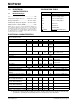
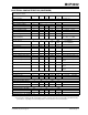
ELECTRICAL CHARACTERISTICS (CONTINUED)
All parameters apply at V
DD
= 5.5V, V
SS
= 0V, T
AMB
= -40°C to +85°C, f
SAMPLE
= 100 ksps and f
CLK
= 18*f
SAMPLE
unless otherwise noted.
Parameter Sym Min. Typ. Max. Units Conditions
Note 1: This parameter is established by characterization and not 100% tested.
2: Because the sample cap will eventually lose charge, effective clock rates below 10 kHz can affect linearity
performance, especially at elevated temperatures. See Section 6.2 for more information.