
Data Sheet

PCA9685 All information provided in this document is subject to legal disclaimers. © NXP B.V. 2010. All rights reserved.
Product data sheet Rev. 3 — 2 September 2010 7 of 51
NXP Semiconductors
PCA9685
16-channel, 12-bit PWM Fm+ I
2
C-bus LED controller
• PCA9564 (0000 000) or PCA9665 (1110 000) slave address which is active on
start-up
• ‘reserved for future use’ I
2
C-bus addresses (0000 011, 1111 1XX)
• slave devices that use the 10-bit addressing scheme (1111 0XX)
• slave devices that are designed to respond to the General Call address (0000 000)
which is used as the software reset address
• High-speed mode (Hs-mode) master code (0000 1XX)
The last bit of the address byte defines the operation to be performed. When set to logic 1
a read is selected, while a logic 0 selects a write operation.
7.1.2 LED All Call I
2
C-bus address
• Default power-up value (ALLCALLADR register): E0h or 1110 000X
• Programmable through I
2
C-bus (volatile programming)
• At power-up, LED All Call I
2
C-bus address is enabled. PCA9685 sends an ACK when
E0h (R/W
= 0) or E1h (R/W = 1) is sent by the master.
See Section 7.3.7 “
ALLCALLADR, LED All Call I
2
C-bus address” for more detail.
Remark: The default LED All Call I
2
C-bus address (E0h or 1110 000X) must not be used
as a regular I
2
C-bus slave address since this address is enabled at power-up. All the
PCA9685s on the I
2
C-bus will acknowledge the address if sent by the I
2
C-bus master.
7.1.3 LED Sub Call I
2
C-bus addresses
• 3 different I
2
C-bus addresses can be used
• Default power-up values:
– SUBADR1 register: E2h or 1110 001X
– SUBADR2 register: E4h or 1110 010X
– SUBADR3 register: E8h or 1110 100X
• Programmable through I
2
C-bus (volatile programming)
• At power-up, Sub Call I
2
C-bus addresses are disabled. PCA9685 does not send an
ACK when E2h (R/W
=0) or E3h (R/W= 1), E4h (R/W = 0) or E5h (R/W =1), or
E8h (R/W
= 0) or E9h (R/W = 1) is sent by the master.
See Section 7.3.6 “
SUBADR1 to SUBADR3, I
2
C-bus subaddress 1 to 3” for more detail.
Remark: The default LED Sub Call I
2
C-bus addresses may be used as regular I
2
C-bus
slave addresses as long as they are disabled.
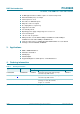
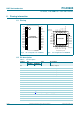
Fig 4. Slave address
R/W
002aad16
8
1 A5 A4 A3 A2 A1 A0
hardware selectable
slave address
fixed